27
20041904
Start-up, calibration and operation of the burner
6.1 Notes on safety for the first start-up
6.2 Adjustments prior to ignition
Combustion head adjustment is already described on page 21.
In addition, the following adjustments must also be made:
➤
open manual valves upline from the gas train.
➤
Adjust the minimum gas pressure switch to the start of the
scale.
➤
Adjust the maximum gas pressure switch to the end of the
scale.
➤
Adjust the air pressure switch to the start of the scale.
➤
Purge the air from the gas line.
We recommend using a plastic tube routed outside the build-
ing and to purge air until gas is smelt.
➤
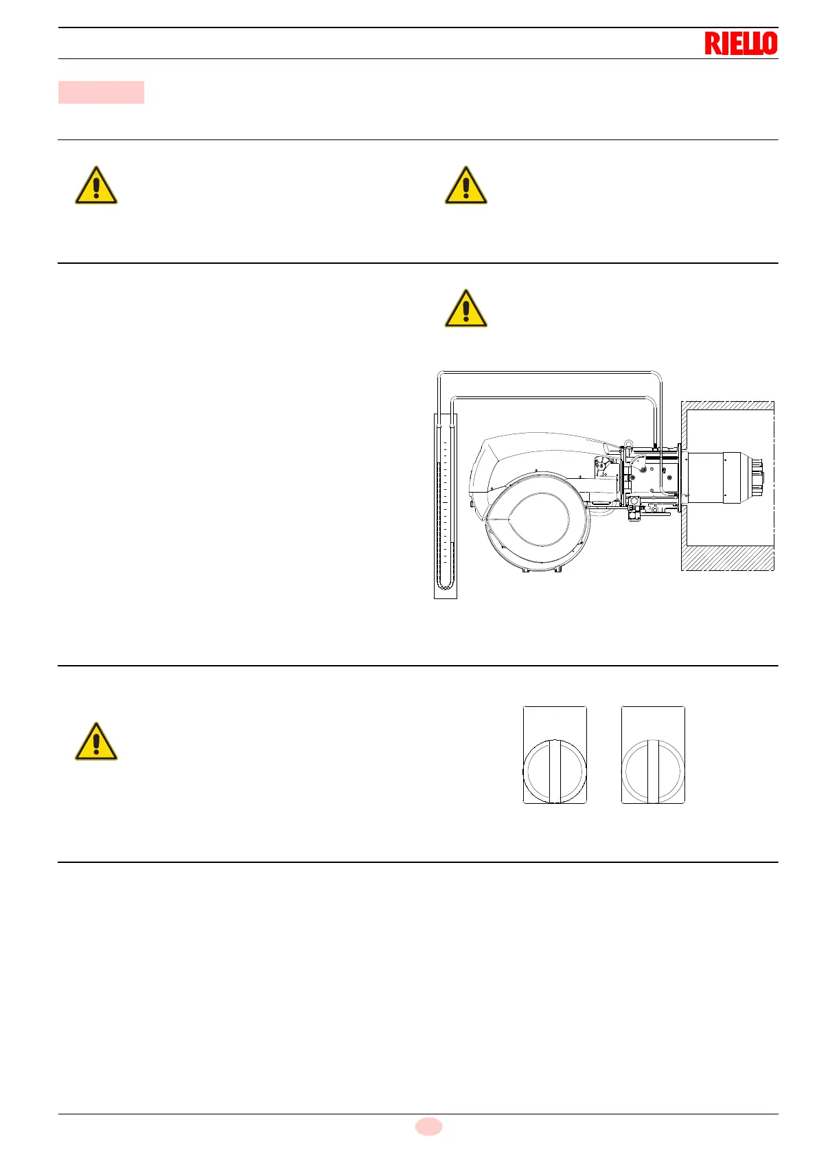
Fit a U-type pressure gauge or a differential pressure gauge
(Fig. 24), with socket (+) on the gas pressure of the pipe
coupling and (-) in the combustion chamber.
The manometer readings are used to calculate MAX burner
output using the Tab. N.
➤
Connect two lamps or testers to the two gas line solenoids to
check the exact moment in which voltage is supplied. This
operation is unnecessary if each of the two solenoids is
equipped with a pilot light that signals voltage passing
through.
6.3 Burner start-up
Close the thermostats/pressure switches and turn the switch 1)
(Fig. 25) to position “
MAN
”.
6.4 Burner ignition
Once the above steps are complete, the burner should light.
If the motor starts up, but the flame does not appear and the con-
trol box goes into lockout, reset it and wait for a new ignition at-
tempt.
If ignition does not occur, it may be that gas is not reaching the
combustion head within the safety time period of 3 seconds. In
this case, increase gas ignition delivery.
The arrival of gas at the pipe coupling is indicated by the U-type
pressure gauge (Fig. 24).
Once the burner has ignited, proceed with the global adjustment
of the burner.
6 Start-up, calibration and operation of the burner
The first start-up of the burner must be carried out
by qualified personnel, as indicated in this manual
and in compliance with the standards and regula-
tions of the laws in force.
Check the correct working of the adjustment, com-
mand and safety devices.
Before starting up the burner, it is good practice to
adjust the gas train so that ignition takes place in
conditions of maximum safety, i.e. with gas deliv-
ery at the minimum.
Make sure that the lights or testers connected to
the solenoids, or the pilot lights on the solenoids
themselves, indicate that no voltage is present.
If voltage is present, stop the burner
immediately
and check the electrical wiring.