31
20041904
Maintenance
Combustion
If the combustion values measured before starting maintenance
do not comply with applicable legislation or do not indicate effi-
cient combustion, consult the Tab. O or contact our Technical
Support Service to implement the necessary adjustments.
It is advisable to set the burner according to the type of gas used
and following the indications in Tab. O.
Tab. O
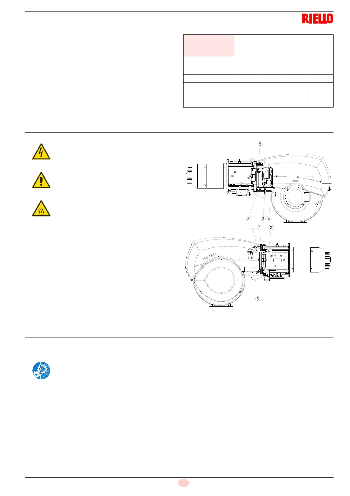
7.3 Opening the burner
➤
Remove the tie-rod 1)(Fig. 31) of the head movement lever,
undoing the nut 2).
➤
Disconnect the socket 3) of the gas servomotor.
➤
Disconnect the socket 4) of the gas pressure switch.
➤
Remove the screws 5).
At this point, it is possible to open the burner on the hinge.
7.4 Closing the burner
Refit following the steps described but in reverse order; refit all
burner components as they were originally assembled.
EN 676
Air excess
Max. output
λ ≤ 1.2
Min. output
λ ≤ 1.3
GAS
CO
2
theoretic
al max. 0% O
2
CO
2
% Calibration
CO
NO
X
λ = 1.2 λ = 1.3 mg/kWh mg/kWh
G 20 11.7 9.7 9.0
≤
100
≤
170
G 25 11.5 9.5 8.8
≤
100
≤
170
G 30 14.0 11.6 10.7
≤
100
≤
230
G 31 13.7 11.4 10.5
≤
100
≤
230
Disconnect the electrical supply from the burner
by means of the main system switch.
Close the fuel interception tap.
Wait for the components in contact with heat
sources to cool down completely.
After carrying out maintenance, cleaning or
checking operations, reassemble the hood and all
the safety and protection devices of the burner.