20041904
20
Installation
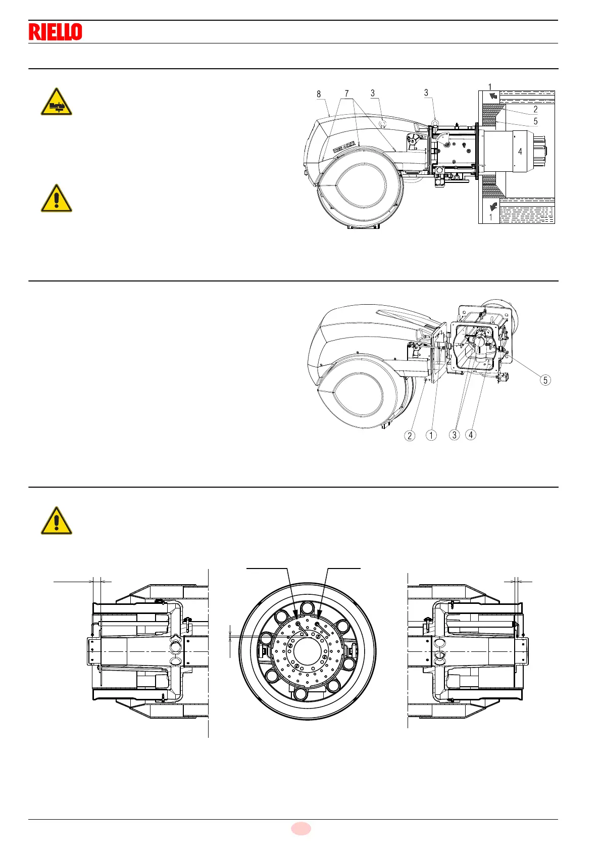
5.7 Securing the burner to the boiler
➤
Fit the heat insulation supplied onto the blast tube (4)
(Fig. 12).
➤
Fit the entire burner onto the boiler hole prepared previously
(Fig. 11), and fasten with the screws supplied.
5.8 Access to head internal part
➤
After you have uncoupled the the head movement lever tie-
rod 1) and removed the 4 fixing screws 2), open the burner
on the hinge (Fig. 13),
➤
Unhook the probe cables and electrode 3).
➤
Tighten the underneath part of the elbow 4) until it is
released from its housing.
➤
Remove the internal part of the head 5).
5.9 Probe-electrode position
Prepare a suitable lifting system using the rings
3)(Fig. 12), after removing the fixing screws 7) of
the casing 8).
The seal between burner and boiler must be
airtight.
Check that the probe and the electrode are placed
as in Fig. 14, according to the dimensions indicat-
ed.
Fig. 14
ProbeElectrode
D11735