13
20041904
Technical description of the burner
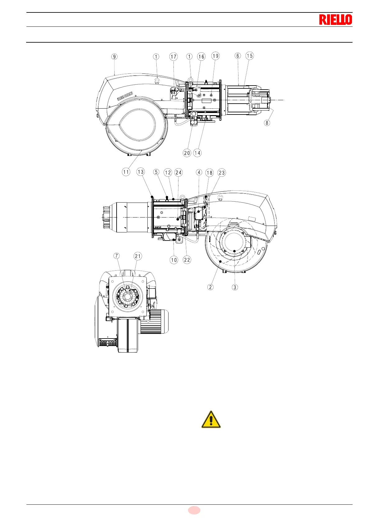
4.10 Burner description
1 Lifting rings
2 Fan
3 Fan motor
4 Air damper servomotor
5 Combustion head gas pressure test point
6 Combustion head
7 Ignition electrode
8 Flame stability disc
9 Electrical panel casing
10 Gas butterfly valve servomotor
11 Fan air inlet
12 Pipe coupling
13 Gasket for boiler fixing
14 Gas butterfly valve
15 Shutter
16 Combustion head movement lever
17 Air damper movement gears
18 Air pressure switch (differential operating type)
19 Combustion head air pressure test point
20 Maximum gas pressure switch with pressure test point
21 Flame sensor probe
22 Hinge for opening the burner
23 Pressure test point for air pressure switch “+”
24 Pressure test point for air pressure switch “-”
The burner can be opened to the right or to the left
without links to the fuel supply side.
When the burner is closed, the hinge can be refit-
ted on the opposite side.