Do you have a question about the Rigol DG4000 Series and is the answer not in the manual?
Legal statement about content ownership.
Information about RIGOL's registered trademark.
Identifier for the manual.
Legal disclaimers and usage restrictions.
Conformance to standards.
Information for customer support.
Key safety precautions before operation.
Importance of using the correct power cord.
Essential step for electrical safety.
Adhering to device ratings to prevent hazards.
Measures to protect against overvoltage.
Procedure for power fuse replacement.
Warning against operating with panels removed.
Precaution against touching exposed components.
Procedure for handling suspected instrument failures.
Importance of adequate ventilation for device health.
Warning against operating in humid environments.
Precaution for hazardous environments.
Maintaining surface cleanliness for device integrity.
Measures to prevent electrostatic discharge damage.
Care during transportation to prevent damage.
Explanation of terms and symbols used for safety.
Advice on instrument storage and environmental conditions.
Steps for cleaning the instrument's exterior.
Guidance on recycling and responsible disposal.
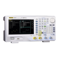
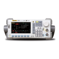
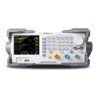
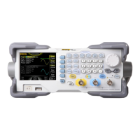
Key functionalities and capabilities of the DG4000 series.
Lists the main chapters and their topics.
Checks for shipping damage, instrument condition, and accessories.
Instructions for unfolding or folding the instrument's support legs.
Graphical representation of the instrument's physical size.
Description of the instrument's front panel controls and indicators.
Description of the instrument's rear panel connectors and inputs.
Procedure for connecting the instrument to AC power.
Explanation of the instrument's display elements and status indicators.
How to input parameters using the numeric keyboard and knob.
Functionality of navigation keys and the rotary knob.
Accessing context-sensitive help information.
Instructions for securing the instrument at a fixed location.
Procedures for installing the instrument in a 19-inch rack.
How to choose between CH1, CH2, or dual-channel output.
Selecting Sine, Square, Ramp, Pulse, or Noise waveforms.
Adjusting the frequency parameter for output waveforms.
Setting the amplitude of the output waveform.
Adjusting the DC offset for the waveform.
Setting the initial phase of the waveform.
Synchronizing the phase of two output channels.
Adjusting the duty cycle for square waveforms.
Adjusting the symmetry for ramp waveforms.
Configuring pulse width, edge times, and delay.
Activating the waveform output from the selected channel.
Step-by-step guide to generating a specific pulse waveform.
Activating the arbitrary waveform generation function.
Enabling sequential output of waveform points.
Choosing from built-in, stored, or volatile arbitrary waveforms.
Defining custom waveforms using points or blocks.
Modifying existing built-in or stored arbitrary waveforms.
Understanding harmonic generation based on Fourier transform.
Configuring base waveform settings for harmonic output.
Specifying the highest order of harmonic to be generated.
Choosing between even, odd, all, or user-defined harmonic orders.
Adjusting the amplitude for each harmonic order.
Setting the phase for each harmonic order.
Amplitude Modulation configuration.
Frequency Modulation configuration.
Phase Modulation configuration.
Amplitude Shift Keying modulation setup.
Frequency Shift Keying modulation setup.
Phase Shift Keying modulation setup.
Binary Phase Shift Keying modulation setup.
Quadrature Phase Shift Keying modulation setup.
3-Frequency Shift Keying modulation setup.
4-Frequency Shift Keying modulation setup.
Oscillation Shift Keying modulation setup.
Pulse Width Modulation setup.
Activating the frequency sweep function.
Setting the start and end points for frequency sweep.
Defining sweep boundaries using center frequency and span.
Selecting between Linear, Log, or Step sweep modes.
Setting the duration for the frequency sweep.
Time taken to return to start frequency after sweep completion.
Setting a specific frequency point for a mark signal.
Duration output stays at the start frequency after sweep begins.
Duration output stays at the end frequency after sweep completes.
Selecting internal, external, or manual trigger for sweep.
Configuring the edge type for trigger output signals.
Activating the burst output function.
Selecting N Cycle, Infinite, or Gated burst modes.
Setting the starting phase of the burst waveform.
Time between consecutive bursts (N Cycle, internal trigger).
Polarity setting for gated burst mode.
Time from trigger to burst start (N Cycle, Infinite).
Selecting internal, external, or manual trigger for burst.
Configuring the edge type for trigger output signals.
Activating the frequency counter function.
Configuring trigger sensitivity, level, impedance, and coupling.
Enabling and configuring statistical analysis of measurements.
Understanding internal (C Disk) and external (D Disk) memory.
Choosing between State, Arb, Txt, Csv, or All file types.
Switching between directory and file browsing modes.
Performing Save, Read, Copy, Paste, Delete, and New Directory operations.
Accessing the Utility menu for configuration.
Configuring channel-specific parameters like Sync and Polarity.
Setting up USB and LAN parameters for remote control.
Adjusting system-wide parameters like language and display format.
Saving screen content to USB storage.
Linking parameters (frequency, phase, amplitude) between channels.
Copying or swapping channel states or waveform data.
Assigning a shortcut key to a frequently used waveform.
Resetting the instrument to factory or user-preset states.
Communicating with the instrument via USB or LAN using SCPI.
Controlling the instrument via programming or PC software.
Using SCPI commands with NI-VISA for control.
Controlling the instrument using PC software like Ultra Sigma.
Solutions for a dark or blank screen after power-on.
Troubleshooting when settings are correct but no output occurs.
Steps to resolve issues with USB device recognition.
Overview of channels, frequency, and sample rate.
List of standard and arbitrary waveform types supported.
Detailed frequency ranges for different waveform types.
Specs for rise/fall time, overshoot, duty cycle, jitter for Square, Ramp, Pulse.
Specifications for arbitrary waveform length, resolution, and sample rate.
Harmonic order, type, amplitude, and phase settings.
Amplitude range, accuracy, and flatness into 50 Ω load.
Detailed parameters for AM, FM, PM, ASK, FSK, PSK, BPSK, QPSK, 3FSK, 4FSK, OSK, PWM.
Specifications for burst count, phase, period, and trigger settings.
Parameters for sweep type, direction, frequency, and trigger.
Counter function, resolution, range, and measurement items.
Input range, bandwidth, impedance, and trigger sensitivity.
Trigger input and output signal specifications.
Phase offset, external reference, and internal reference specs.
Specifications for sync signal output.
Power voltage, consumption, fuse, and display details.
List of available models, standard accessories, and optional items.
RIGOL's warranty policy and service information.
Contact information for documentation feedback.