Linear installation guide 13563-B 02-19 | 23
Gas pressure setting
Checking the supply pressure
1. Remove the inlet test point screw and
connect the manometer hose.
2. Press the heater On/Off button to start the
ignition sequence, ensuring the correct
inlet pressure is available with all other gas
appliances operating on high.
3. Press the heater On/Off button to stop the
heater operation.
4. Disconnect the manometer hose and
replace the inlet test point screw.
Before commencing with the setting of the
burner pressures the correct ue length must
be set. The appliance is factory set for short
ue installations (refer image on p.1), with the
dip switch set to S-F (short ue). For a long ue
installation, set the dip switch to L-F (long ue).
Setting the pilot pressure
1. Remove the pilot test point screw and
connect the manometer hose.
2. Press the heater On/Off button to start the
ignition sequence, ensuring the correct
inlet pressure is available with all other gas
appliances operating on high.
3. Press the test button twice, the heater will
light to main burner on its lowest setting
(stage 1) and the display will show PL.
4. Adjust the pilot pressure as required by
manually adjusting the pilot pressure
adjustment screw. Press the On/Off button
to stop the heater operation.
5. Disconnect the manometer hose and
replace the pilot test point screw.
Setting the operating pressure
1. Remove the main burner test point screw
and connect the positive manometer hose.
2. Press the heater On/Off button to start the
heater.
3. Press the test button twice, the heater will
light to the main burner on its lowest setting
(stage 1) and the digital display will show
PL.
4. Press the up or down buttons to set the
pressure for the appropriate gas type. Press
the set button once to save the setting.
5. The display will now show PF (main burner
stage 3). Press the up or down buttons to
set the pressure for the appropriate gas
type. Press the set button once to save the
setting.
6. The display will show PA (main burner
stage 4). Press the up and down buttons
to set the pressure for the appropriate gas
type. Press the set button once to save the
setting.
7. The display will show PH (main burner
stage 7). Press the up or down buttons to
set the differential for the appropriate gas
type. Press the set button once to save the
setting.
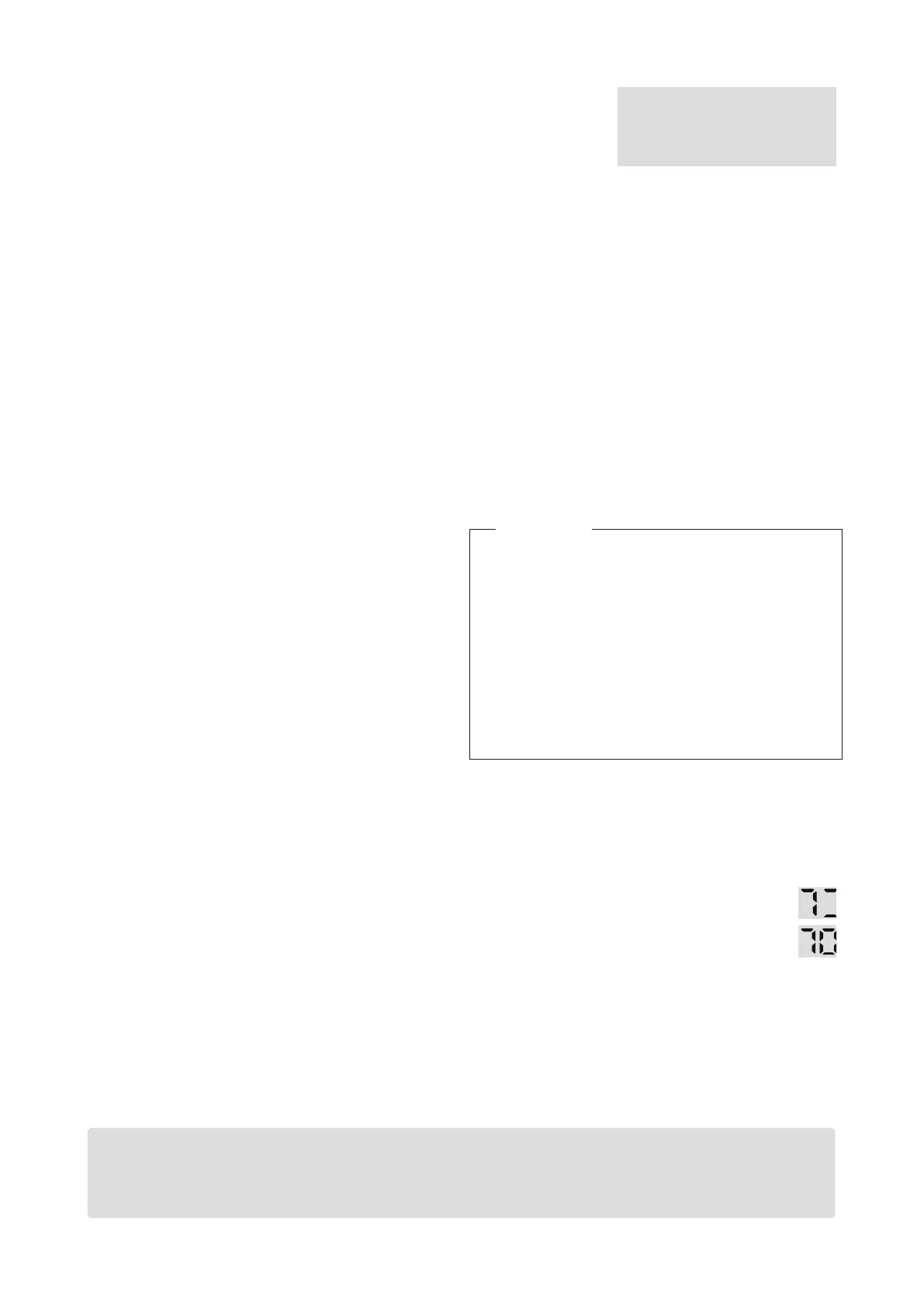
8. The display will show 7 and two
dashes (800, 1000) or 7 and six
dashes (1500). If the display does not
change, then there is a
commissioning error—repeat steps.
9. Press the on/off button to stop the unit.
Remove the manometer hose and replace the
gas control test point screw. Commissioning is
now complete.
Sequence will vary slightly depending on the model:
Linear 800, 1000: PL > PH Linear 1500: PL > PF > PA > PH
1500 only
Please note
After the gas code is displayed the LED will show
0. This is the room thermistor offset that is
preset to
0 (range 0-15 °C). This is typically only adjusted in troubleshooting scenarios, and is
not part of commissioning.
PL = main burner on low
PF = main burner on high
PA = all burners on low
PH = all burners on high
 Loading...