12 | Linear installation guide 13563-B 02-19
The main points governing location are ueing and warm air distribution.
For the following framing dimensions it is important to be aware that the studs are offset—
the cavity needs to be framed based on the centreline of the glass, not the opening size.
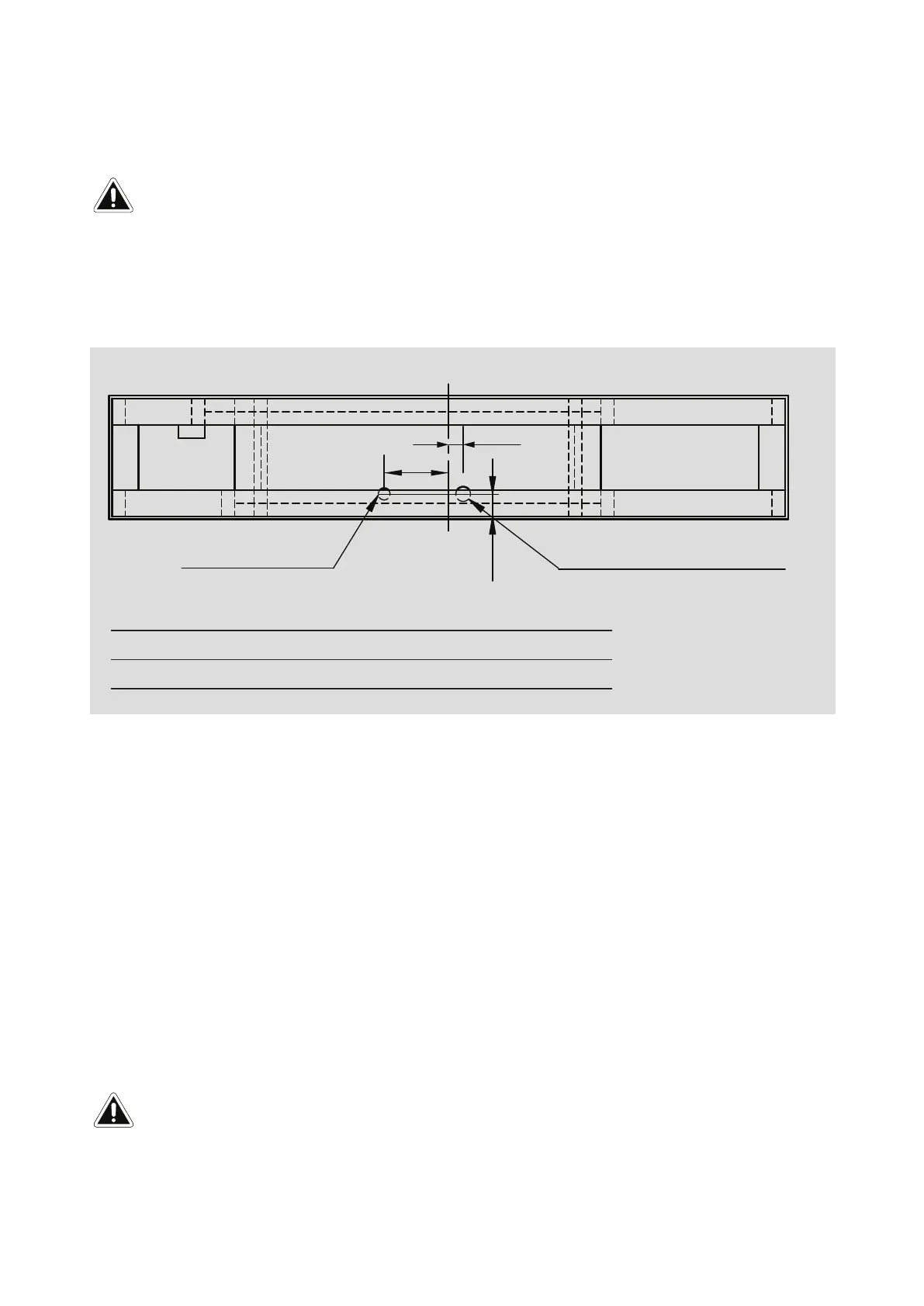
Base board and connection cutouts
To ensure everything lines up and ts properly it’s recommended that on the base the following
dimensions are pencilled; glass centreline, unit depth centreline, feet position, gas and room
thermistor cutouts.
77
A
220
Gas supply hole
Room thermistor Ø 40 mm
Glass centreline
Assumes 10 mm wall board
Linear 800 Linear 1000 Linear 1500
A (room supply air) 50 mm 50 mm 255 mm
Cavity ventilation
Ventilation of at least 2000 mm
2
must be provided into the installation cavity, ideally below the base
of the re.
This is to provide room air at ambient room temperature to the re thermistor located in
the base of the re. Ventilation can be via a vent or an open toe kick at the base of the cavity—it
must be in the same room as the re.
Additionally the top of the cavity must be ventilated into the room or another space. This ventilation
opening must also be at least 2000 mm
2.
This opening prevents heat build up inside the cavity,
which if left unvented could cause damage to wall surfaces or coverings and/or cause the re to
cut out.
Additional framing notes
• Wallboard is set 1 mm back from the front edge of the lips to allow for a slim edge plaster nish.
• To ensure the appliance performs correctly, without rattling, the Linear MUST BE installed on
a at level support base. The joists must be cable of supporting a minimum of 1.5 times the
weight of the appliance—base panel is also designed to take the weight of the wallboard.
Issues caused by rattling res not installed on a at level base, as detailed in this guide, will
not be covered by warranty.
IMPORTANT
IMPORTANT
Framing dimensions
 Loading...