28 | Linear installation guide 13563-B 02-19
Installing the wall lining
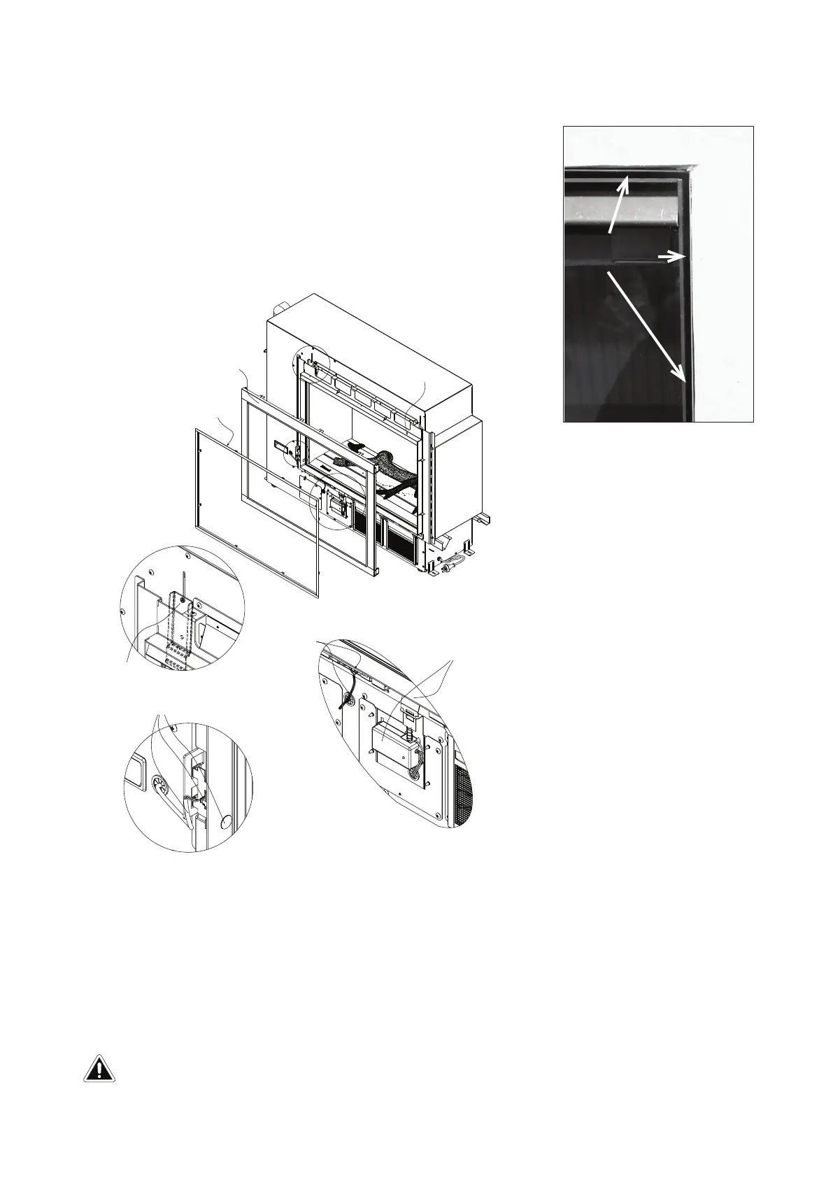
There are some aspects of the wall lining installation that are critical
to the safe operation of the appliance. An air gap of at least 3 mm
around the re is critical to the safe operation of the Linear to ensure
air ow in and around the unit.
Below is an image to highlight the position and names of the different
Linear framing components. Adapt as necessary, depending on the
wall lining being installed.
Additional notes
Combustible wall linings, if installed according to the information in this guide, provide a safe
surround for the Linear. However please be aware that the wall will go through hot and cold cycles
and can reach up to 80 °C. This could impact on the durability of the timber and/or wallpaper
finishes.
The wallboard support panel is intended to be used as a fixing point for the wall lining. It is
recommended that screws are not used as a permanent fixing method along the top edge of the
fire.
If screws are used (maximum length 25 mm) around the edge, ensure they do not interfere
with the working parts of the fire (latches, IR receiver, On/Off button).
C
B
A
Lips
C (1 : 3)
B (1 : 2)
A (1 : 3)
Wallboard support rails
(adjustable/removable)
Finishing trim
(accessory)
Glass retainer
latch
IR receiver lens
and harness
Wi-Fi module assembly
ON/OFF button,
PCB, and harness
IMPORTANT
Wall lining UP TO lips of unit
3 mm air gap
around unit
 Loading...