Rinnai 38 Multi Split Type AC
Outdoor Unit
Installation
The largest
system to be
connected to
Circuit A
Notes On Drilling Hole In Wall
You must drill a hole in the wall for the
refrigerant piping, and the signal cable that will
connect the indoor and outdoor units.
1.
Determine the location of the wall hole
based on the location of the outdoor unit.
2. Using a 65-mm core drill, drill a hole
in the wall.
NOTE: When drilling the wall hole, make
sure to avoid wires, plumbing, and other
sensitive components.
3.
Place the protective wall cu in the hole.
This protects the edges of the hole and
helps seal it when you nish the
installation process.
Size
Outdoor Unit
Dimensions (mm)
Mounting
Dimensions (mm)
kW W x D x H Distance A Distance B
7 890 x 342 x 673 663 354
9 /11 946 x 410 x 810 673 403
Rows of series installation
The relations between H, A and L are
as follows.
L A
L ≤ 1/2H
25 cm or more
L ≤ H
1/2H < L ≤ H
30 cm or more
L > H
Can not be installed
L
H
300 cm or more
150 cm
mo
60 cm
A
or re
or more
m
25 cm
25 cm
or ore
or more
When selecting a 7.0kW Indoor Unit
(unit: mm)
Indoor Unit capacity
(kW)
Liquid Gas
2.0 / 2.6 / 3.5 6.35 9.53
3.5 / 5.0 / 6.0 6.35 12.70
7.0 9.53 15.88
The 7.0kW indoor unit can only be connected with
an A circuit. If there are two 7.0kW indoor units,
they can be connected with A and B circuits.
Connective pipe size of an A and B circuit
Rinnai 8 Multi Split Type Air Conditioner
Outdoor unit
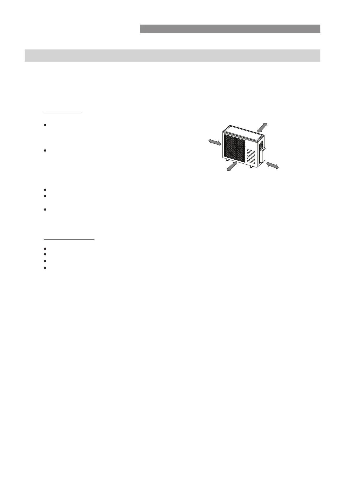
More than 10cm
If an awning is built over the outdoor unit to minimise
direct sunlight or rain exposure, ensure that the
More than 30cm
air paths and heat radiation from the condenser is
uninhibited.
Ensure that the clearance to the back of the
unit is more than 10cm and left side is more
More than 60cm
than 30cm. The front of the unit should
have more than 65cm of clearance and the
connection side (right side) should have more
More than 65cm
than 60cm of clearance.
Do not place animals or plants in the path of the air inlet or outlet.
Take the unit’s operating weight into account and select a suitable position to minimise noise
and vibration both internally and externally.
Select a suitable position so that the air discharge and noise from the unit does not disturb neighbours.
Selecting installation position
Read completely, then follow step by step.
Indoor unit
If the outdoor unit is installed on a roof structure, ensure it is installed on a secure level base.
Ensure the roof structure and securing method are adequate for the unit location.
Consult local codes and regulations regarding roof mounting.
If the outdoor unit is installed on roof structures or external walls, this may result in
excessive noise and vibration, it may also be classed as a non serviceable installation, and void
Roof installation
INSTALLATION INSTRUCTIONS
More than 15cm
WALL MOUNTED -
the manufacturers warranty.
also refer to the Installation Manual accompanying the Wall Mounted Unit
Do not expose the indoor unit to external heat or steam.
More than 12cm
More than 12cm
Select a position where there are no obstacles
in front or around the unit.
Make sure that the condensate drain and pipework can
be conveniently routed.
Do not install near doorways and kitchen.
Ensure that the clearance to the left and the right
of the unit is more than 12cm.
Use a stud finder to locate studs for secure mounting and prevent damage to the wall.
The indoor unit should be installed allowing a minimum clearance of 15cm from the ceiling above.
Any variations in pipe length may require adjustment to the refrigerant charge.
Install away from direct sunlight . The sun may fade the plastic cabinet and af fect its appearance.
If unavoidable, adequate sunlight prevention should be taken into consideration.
INSTALLATION INSTRUCTIONS
Wall Mounted Installation (Outdoor)
OUTDOOR UNIT INSTALLATION
WALL MOUNTED - Also refer to the Installation
Manual accompanying the Wall Mounted Unit
Selecting installation position.
 Loading...