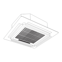
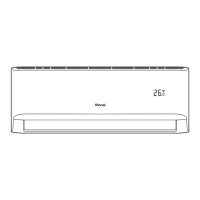
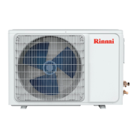
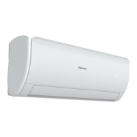
Rinnai 44 Multi Split Type AC
WIRING
Outdoor Unit Wiring
WARNING
Before performing any electrical or wiring
work, turn o the main power to the
system.
1. Prepare the cable for connection
a. You must rst choose the right cable
size. Be sure to use H07RN-F cables.
Minimum Cross-Sectional Area of
Power and Signal Cables (For reference)
Rated Current of
Appliance (A)
Nominal Cross-Sectional
Area (mm²)
> 3 and ≤ 6
0.75
> 6 and ≤ 10
1
> 10 and ≤ 16
1.5
> 16 and ≤ 25
2.5
> 25 and ≤ 32
4
> 32 and ≤ 40
6
Using a wire crimper, crimp u-lugs on the
ends.
b. Using wire strippers, strip the rubber
jacket from both ends of the signal cable
to reveal approximately 15cm of wire.
c.
Strip the insulation from the ends.
NOTE: When connecting the wires, strictly
follow the wiring diagram found inside the
electrical box cover.
CHOOSE THE RIGHT CABLE SIZE
NOTE: Choose the cable type
according to the local electrical
codes and regulations.
NOTE: The schematics are for
explanation purposes only. Your
machine may be slightly different.
The actual shape shall prevail.
The size of the power supply cable, signal
cable, fuse, and switch needed is determined
by the maximum current of the unit. The
maximum current is indicated on the nameplate
located on the side panel of the unit. Refer to
this nameplate to choose the right cable, fuse,
or switch.
NOTE: Please choose the right cable
size according to the Minimum Circuit
Amperage indicated on the nameplate
of the unit.
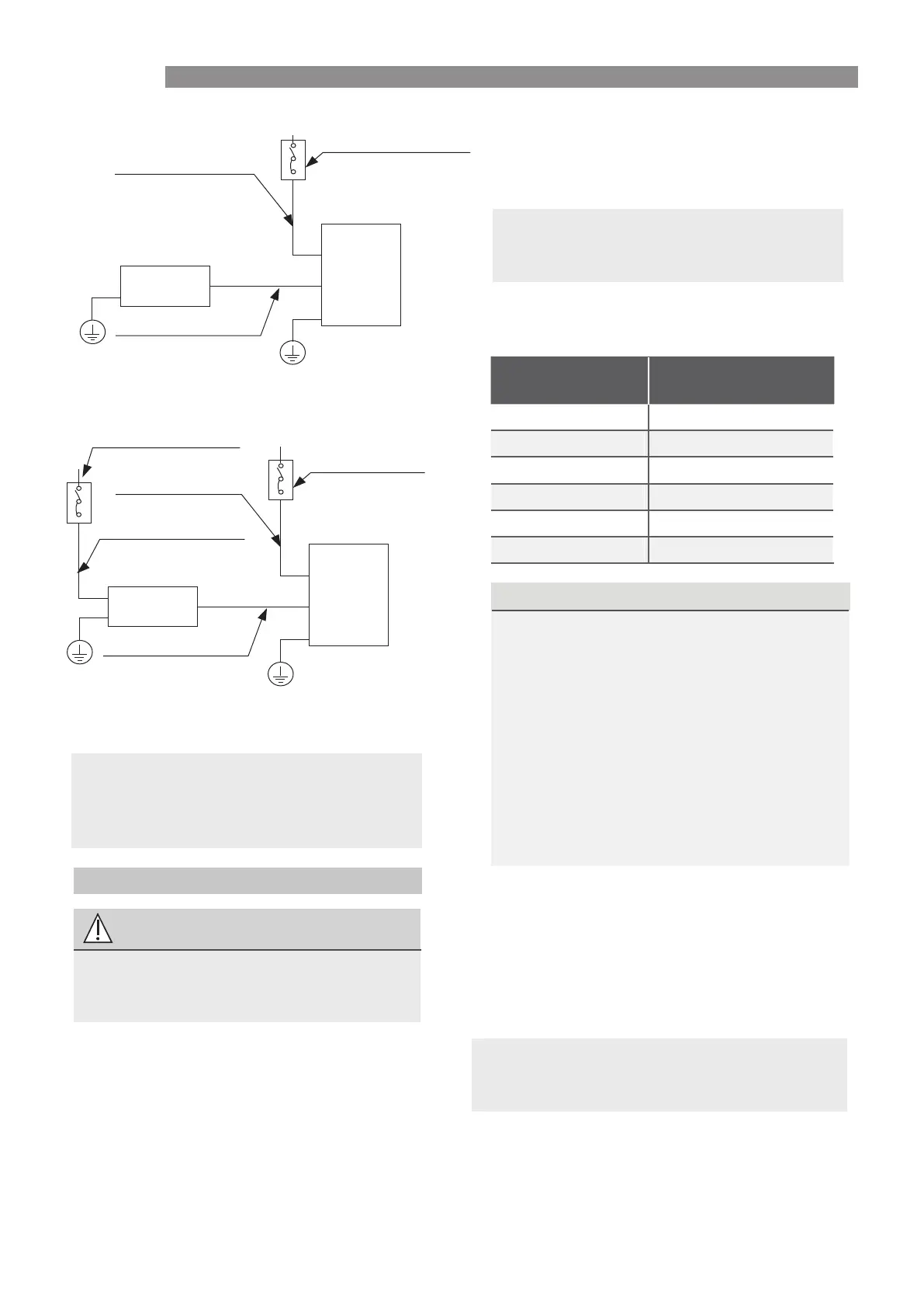
(B)
Isolation switch
Indoor unit power wires
(purchased seperately)
Indoor unit
Outdoor unit
Indoor & Outdoor
connective wires
(purchased seperately)
(C)
Isolation switch
(purchased seperately)
Isolation switch
Indoor unit power wires
(purchased seperately)
Outdoor unit power wires
Indoor unit
Outdoor unit
Indoor & Outdoor
connective wires
(purchased seperately)
d.
Wiring Figure
3. Connect the u-lugs to the terminals Match the wire colors/labels with the labels on
the terminal block, and rmly screw the u-lug of each wire to its corresponding terminal.
4. Clamp down the cable with designated cable clamp.
5. Insulate unused wires with electrical tape. Keep them away from any electrical or metal parts.
6. Reinstall the cover of the electric control box.
CAUTION
Connect the connective cables to the terminals, as identied, with their matching numbers
on the terminal block of the indoor and outdoor units. For example, Terminal L1(A) of the
outdoor unit must connect with terminal L1/1 on the indoor unit. The outdoor unit can
match dierent types of indoor unit, the numbers on the terminal block of the indoor unit
may be slightly dierent. Please pay special attention while connecting the wire.
OPTIONAL
2.
Cover
Screw
Remove the electric cover of the outdoor unit. If there is no cover on the outdoor unit, take
o the bolts from the maintenance board and remove the protection board.
or
or
NOTE: Run the main power cord through the lower line-outlet of the cord clamp.
NOTE: For quick-connector models, please refer to “Owner’s Manual & Installation Manual”
packed with the indoor unit.
 Loading...