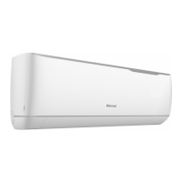
Rinnai 17 Multi Split Type AC
INDOOR INSTALLATION
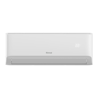
Rinnai 13 Multi Split Type Air Conditioner
INSTALLATION INSTRUCTIONS
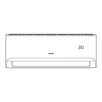
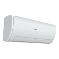
Air outlet
Air inlet
Air filter(on selected models)
Drain hose
Electric control cabinet
Refrigerant connecting pipe
Indoor Unit Parts
Safety Precautions
• Securely install the indoor unit on a structure
that can sustain its weight. If the structure is
too weak, the unit may fall causing personal
injury, unit and property damage, or even
death
• DO NOT install the indoor unit in a bathroom
or laundry room as excessive moisture can
short the unit and corrode the wiring.
CAUTION
WARNING
• Install the indoor and outdoor units, cables
and wi res at least 1m fr om televisions or
radios to pr
event static or image distortion.
Depending on the appliances, a 1m
distance may not be sufficient.
•
If the indoor unit is installed on a metal
part of the building, it must be grounded.
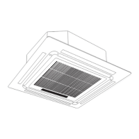
DUCTED INDOOR UNIT
Accessories
Name Shape Quantity
Soundproof / Insulation Sheath
2
Tubing & Fittings
Seal Sponge
1
Outlet Pipe Sheath
Outlet Pipe Sheath
1
Outlet Pipe Clasp
Outlet Pipe Clasp
2
Wired Controller
Wired Controller
1
Other
Display Panel (for testing purposes) 1 (some models)
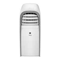
Rinnai 14 Multi Split Type Air Conditioner
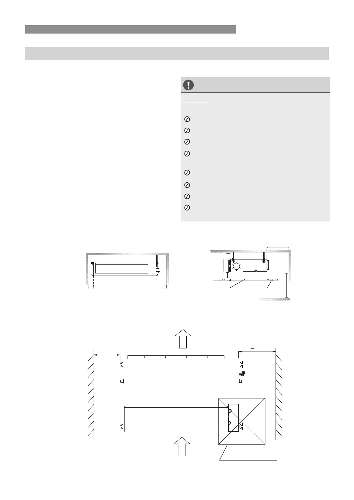
Step 1: Select installation location
The indoor unit should be installed in a location
that meets the following requirements:
Enough room for installation and maintenance.
Enough room for the connecting pipe and
drainpipe.
The ceiling is horizontal and its structure can
sustain the weight of the indoor unit.
The air inlet and outlet are not impeded.
The airflow can fill the entire room.
There is no direct radiation from heaters.
CAUTION
DO NOT install the unit in the following
locations:
Where oil drilling or fracking is taking place.
Coastal areas with high salt content in the air
Near geothermal activity and corrosive gas
Buildings that may experience power
fluctuations
Enclosed spaces
Areas with strong electromagnetic waves
Areas that store flammable materials or gas
Rooms with high humidity, such as
bathrooms or laundry rooms
√
√
√
√
√
√
It is embeded installation.
√
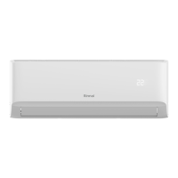
Indoor Unit Installation Instructions
INSTALLATION INSTRUCTIONS
√
Models with a cooling capacity of 2.6 kW to
5 kW only apply to one room.
Strong and durable ceiling
Indoor unit
Left
Right
side
side
Service access
(for removing/replacing unit)
Ceiling
Floor
Maintenance space
Air outlet
Air inlet
60cmx60cm
(Access panel for
maintenance and repairs)
>
30cm
>2cm
B
>2cm
>10cm >30cm
> 30cm
> 20cm
>
250cm
(When no ceiling)
Step 2: Hang indoor unit.
1. Please refer to the following diagrams to locate the four positioning screw bolt holes on the
ceiling. Be sure to mark the paces where you will drill ceiling hook holes.
Air outlet dimensions
Air filter (where fitted)
Descending ventilation opening and mounted hook
Air filter
Electric control box
(unit: mm/inch)
MODELS
Outline dimension
A BC
air outlet opening size
D EF
air return opening size
Size of mounted lug
I
J
G
H
210/8.3 674/26.5880/34.6
249/9.8 774/30.51100/43.3
136/5.4 706/27.8600/23.6
175/6.9 926/36.5700/27.6
190/7.5
228/8.9
920/36.2782/30.8
1140/44.91001/39.4
508/20.0
598/23.5
DINSD261M
200/7.9 506/19.9700/27.6 152/6.0 537/21.1450/17.7 186/7.3 741/29.2599/23.6
360/14.2
Air inlet dimensions
DINSD351M
DINSD501M
DINSD701M
INSTALLATION INSTRUCTIONS
Ducted Indoor Unit Installation
 Loading...