Rinnai 46 Multi Split Type AC
WIRING
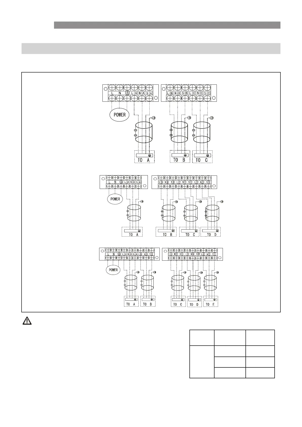
Outdoor Unit Wiring Diagrams
Rinnai 35 Multi Split Type Air Conditioner
ELECTRICAL WIRING
NOTE: Please refer to the following diagrams for the wiring connections for the various models.
Please run the main power cord through the lower line-outlet of the cord clamp.
1) An individual power circuit must be used for this system.
Wiring shall be conducted in accordance with the unit circuit diagram & these instructions.
2) The screws which fasten the wiring within the electrical switchboard may come loose from
r
vibration in transportation. Please ensure that all electrical connections within the unit are sufficiently
tightened. Loose connections may cause overheating at the terminals, leading to an electrical
t
failure or malfunction.
3) Confirm the suitability of the power source.
4) Confirm that electrical capacity is sufficient for the operating current of the system.
5) Ensure that the starting voltage is maintained at more than 90 percent of the rated voltage marked
as marked on the name plate.
6) Confirm that the cable thickness is suitable for the power source specification.
7)
Always use an adequately sized circuit breaker.
8) The issues which may cause voltage drop are for example: vibration/chattering of contractors which
will damage the contact points or blown fuses breaking, overload and/or malfunction of the system.
9) Before accessing the electrical terminals, disconnect all power from the system.
CAUTION
ONE OUTDOOR - THREE INDOOR UNITS
ONE OUTDOOR - FOUR INDOOR UNITS
ONE OUTDOOR - FIVE INDOOR UNITS
L N S L N S L N S
L N S
L N S
L N S
L N S
L N S
L N S
L N S
L N S
Compressor / Power Supply Information
Compressor
start/stop
Stop time Min 3 minutes
Power supply
voltage
Voltage variance
Within +/- 10% of
supply voltage
Voltage drop
Within +/- 15% of
supply voltage
Voltage imbalance
Within +/- 3% of
supply voltage
 Loading...