MASTER MAKING SECTION
THEORY OF OPERATION
GR37705 - 3
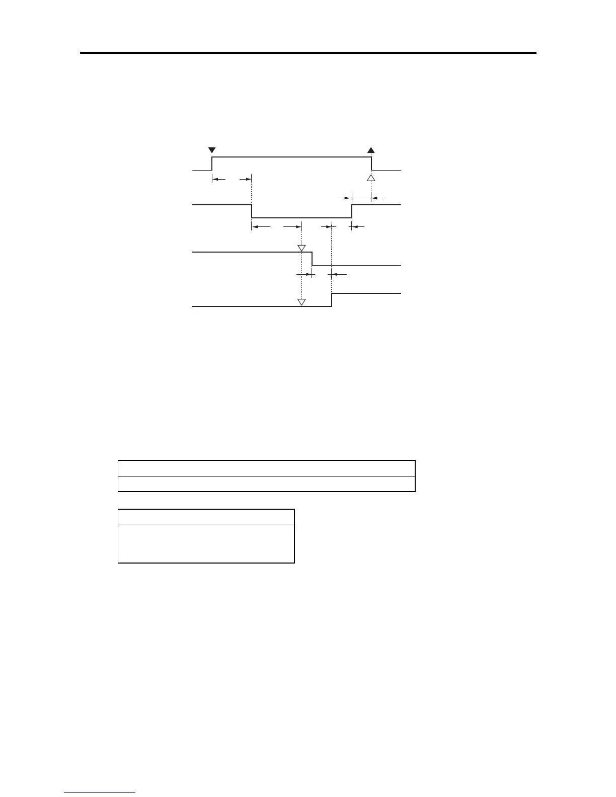
TIMING CHART OF CLAMP PLATE OPENING OPERATION
<1> When A detection sensor is not ON, start operation after A detection of the drum is performed.
<2> When Clamp Safety SW is kept pushed for a period longer than 1.5 seconds from turning ON of the clamp
motor, a clamp error is judged and “T14 CALL SERVICE” appears.
<3> When the 0° angular sensor and the 180° angular sensor are both held OFF or ON for a period longer than
1.5 seconds after Clamp Safety Sw is released, a clamp error is judged and “T3 CALL SERVICE” mes-
sage appears.
<4> When the 180° angular sensor does not get ON even after 2 seconds from turning OFF of the 0° angular
sensor, a clamp error is judged and “T14 CALL SERVICE” appears.
<5> When Clamp Safety SW is not pushed even after 2 seconds from turning ON of the 180° angular sensor,
a clamp error is judged and “T14 CALL SERVICE” appears.
T3 (Clamp Error (1))
• Both 0° angular sensor and 180° angular sensor are turned OFF or ON.
T14 (Clamp Error (2))
• Clamp Safety SW kept pushed.
• The 180° angular sensor not turned ON.
• Clamp Safety SW not pushed.
Clamp motor
<2>
350 ms
Clamp safety motor
<3>
<1>
<4>
<4>
<6>
0° angular sensor
<5>
180° angular sensor
START key ON Master removal operation starts.