1/4-20 x 2-1/4" bolts
nylon washers
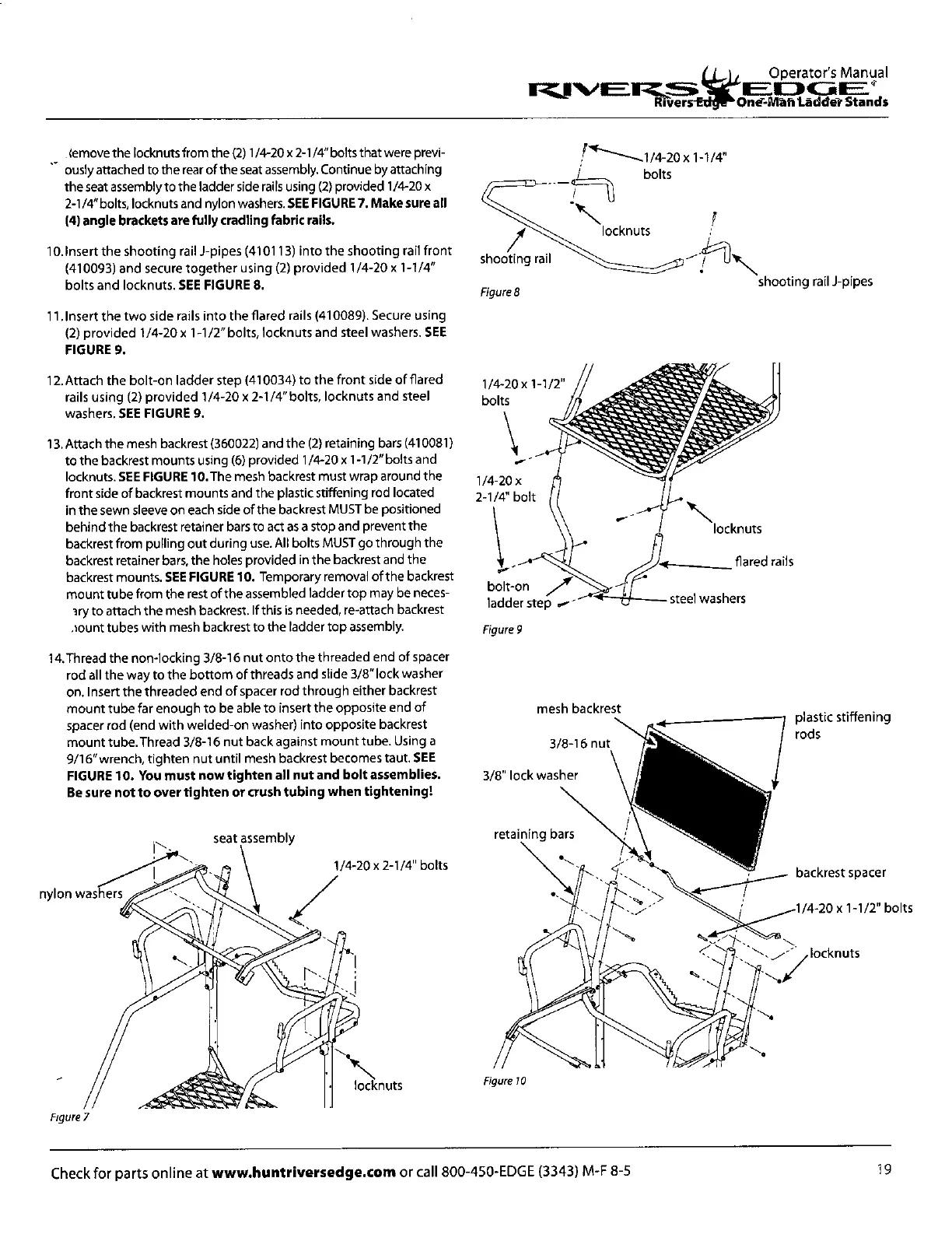
shooting rail
Figure 8
shooting rail J-pipes
1/4_20 x 1-1/4"
bolts
locknuts
locknuts
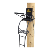
flared rails
steel washers
bolt-on
ladder step ,,-
1/4-20x 1-1/2"
bolts
1/4-20 x
2-1/4" bolt
-..zrzZ"V&I
..:,-......,....
1
%
-
t
.. ...
._..,,
....."2•
1-,.
.."Vt.Z.t
.
.;;*.',„..*;,....„- Q..,.
...z....4:zz, ,
-1.1. ...Z....Z.
,
-..., ......,.. ... . -
.
,
,.
...t
.
1
1.
-
-.:-
70
.,.
a
...
.,..........", z,,:.
.. .. - -
...,.....
4..
,,,..
..., „.. .
..z.
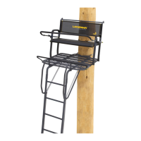
mesh backrest
3/8-16 nut
3/8" lock washer
plastic stiffening
rods
retaining bars
backrest spacer
1/4-20 x 1-1/2" bolts
locknuts
Operators Manual
laILDGE
Biters
E
Oner-Mah Laddet Stands
'c
s
emove the locknuts from the (2)1/4-20 x 2-
1
/
4
" bolts that were previ-
ously attached to the rear of the seat assembly. Continue by attaching
the seat assembly to the ladder side rails using (2) provided 1/4-20 x
2-1/4"bolts, locknuts and nylon washers.
SEE FIGURE 7. Make sure all
(4) angle brackets are fully cradling fabric rails.
Insert the shooting rail 1-pipes (410113) into the shooting rail front
(410093) and secure together using (2) provided 1/4-20 x 1-
1
/
4
"
bolts and locknuts.
SEE FIGURE 8.
Insert the two side rails into the flared rails (410089). Secure using
(2) provided 1/4-20 x 1-1/2" bolts, locknuts and steel washers.
SEE
FIGURE 9.
Attach the bolt-on ladder step (410034) to the front side of flared
rails using (2) provided 1/4-20 x 2-1/4" bolts, locknuts and steel
washers.
SEE FIGURE 9.
Attach the mesh backrest (360022) and the (2) retaining bars (410081)
to the backrest mounts using (6) provided 1/4-20 x 1-1/2" bolts and
locknuts.
SEE FIGURE 10.The
mesh backrest must wrap around the
front side of backrest mounts and the plastic stiffening rod located
in the sewn sleeve on each side of the backrest MUST be positioned
behind the backrest retainer bars to act as a stop and prevent the
backrest from pulling out during use. All bolts MUST go through the
backrest retainer bars, the holes provided in the backrest and the
backrest mounts.
SEE FIGURE 10.
Temporary removal of the backrest
mount tube from the rest of the assembled ladder top may be neces-
iry to attach the mesh backrest. If this is needed, re-attach backrest
.lount tubes with mesh backrest to the ladder top assembly.
14.Thread the non-locking 3/8-16 nut onto the threaded end of spacer
rod all the way to the bottom of threads and slide 3/8" lock washer
on. Insert the threaded end of spacer rod through either backrest
mount tube far enough to be able to insert the opposite end of
spacer rod (end with welded-on washer) into opposite backrest
mount tube.Thread 3/8-16 nut back against mount tube. Using a
9/16" wrench, tighten nut until mesh backrest becomes taut.
SEE
FIGURE 10. You must now tighten all nut and bolt assemblies.
Be sure not to over tighten or crush tubing when tightening!
seat assembly
Figure
?
Figure 9
Figure 10
19
Check for parts online at
www.huntriversedge.com
or call 800-450-EDGE (3343) M-F 8-5