steel washers
tree blade
locknuts
1/4-20 x 2-1/4" bolts
main ladder side rails
flared rails —0-
steel
washers
steel
washers
1/4-20 x 1-1/2" bolts
locknuts
foot platform
1/4-20 x 2-1/4" bolts
locknuts
bolts
i
steel was ers
1/4-20 x 2-1/4"
Phillips head bolts
upper ladder
support tubes
locknuts
steel washers
1/4-20 x 2" bolts
Operator's Manual
Miters
Ed One-Man tackle Stands
O
SEMBLY INSTRUCTIONS (RE631)
Tools needed - two
7
/
1
6" wrenches, Phillips screw driver
IMPORTANT ASSEMBLY TIP. Do not tighten any nut and bolt combinations
completely until all parts are assembled together! Finger tighten plus one
turn of a wrench only! This will temporarily hold the locknut on the bolt while
helping alignment of all parts! Afterall parts are assembled together, all nut
and bolt combinations must be completely tightened.
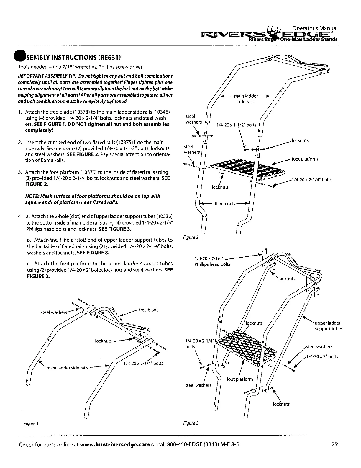
Attach the tree blade (10373) to the main ladder side rails (10346)
using (4) provided 1/4-20 x 2-1/4" bolts, locknuts and steel wash-
ers.
SEE FIGURE 1. DO NOT tighten all nut and bolt assemblies
completely!
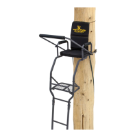
Insert the crimped end of two flared rails (10375) into the main
side rails. Secure using (2) provided 1/4-20 x 1-1/2" bolts, locknuts
and steel washers.
SEE FIGURE 2.
Pay special attention to orienta-
tion of flared rails.
Attach the foot platform (10370) to the inside of flared rails using
(2) provided 1/4-20 x 2-1/4" bolts, locknuts and steel washers.
SEE
FIGURE 2.
NOTE:Mesh surface of foot platforms should be on top with
square ends of platform near flared rails.
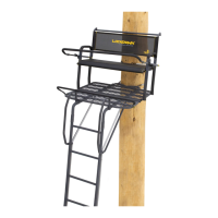
4
a. Attach the 2-hole (slot) end of upper ladder support tubes (10336)
to the bottom side of main side rails using (4) provided 1 /4-20 x2-1/4"
Phillips head bolts and locknuts.
SEE FIGURE 3.
o. Attach the 1-hole (slot) end of upper ladder support tubes to
the backside of flared rails using (2) provided 1/4-20 x 2-1/4" bolts,
washers and locknuts.
SEE FIGURE 3.
c. Attach the foot platform to the upper ladder support tubes
using (2) provided 1/4-20 x 2"bolts, locknuts and steel washers.
SEE
FIGURE 3.
rigure 1
.4—main ladder-----ø-
side rails
Figure 2
Figure 3
Check for parts online at
www.huntriversedge.com
or call 800-450-EDGE (3343) M-F 8-5
29