1/4-20 x 1-1/2"
bolts
locknut
1/4-20 x 1-1/2" bolts
seat rails
locknuts
1/4-20 x 2-1/2" bolts
double flat braces
locknuts
1/4-20 x 2-
1
/
4
"
bolts
bolt-on step
1/4-20 x 2-1/4" bolts
steel washers
Figure 4
spring lock pins
Operator's Manual
rziNtl-C_S
VECDO
Rfvers E
One"-Mab Ladder Stands
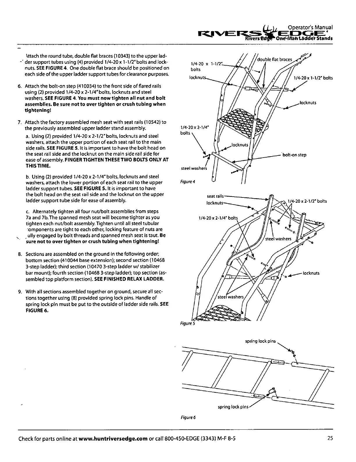
Nttach the round tube, double flat braces (10343) to the upper lad-
-- der support tubes using (4) provided 1/4-20 x 1-1/2" bolts and lock-
nuts.
SEE FIGURE 4.
One double flat brace should be positioned on
each side of the upper ladder support tubes for clearance purposes.
6. Attach the bolt-on step (410034) to the front side of flared rails
using (2) provided 1/4-20 x 2-1/4" bolts, locknuts and steel
washers.
SEE FIGURE 4. You must now tighten all nut and bolt
assemblies. Be sure not to over tighten or crush tubing when
tightening!
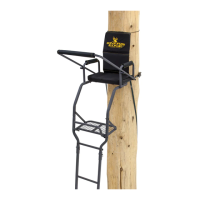
7. Attach the factory assembled mesh seat with seat rails (10542) to
the previously assembled upper ladder stand assembly.
Using (2) provided 1/4-20 x 2-1/2" bolts, locknuts and steel
washers, attach the upper portion of each seat rail to the main
side rails.
SEE FIGURE 5.
It is important to have the bolt head on
the seat rail side and the locknut on the main side rail side for
ease of assembly.
FINGER TIGHTEN THESE TWO BOLTS ONLY AT
THIS TIME.
Using (2) provided 1/4-20 x 2-1/4" bolts, locknuts and steel
washers, attach the lower portion of each seat rail to the upper
ladder support tubes.
SEE FIGURE S.
It is important to have
the bolt head on the seat rail side and the locknut on the upper
ladder support tube side for ease of assembly.
Alternately tighten all four nut/bolt assemblies from steps
7a and 7b. The spanned mesh seat will become tighter as you
tighten each nut/bolt assembly. Tighten until all steel tubular
.
omponents are tight to each other, locking feature of nuts are
ully engaged by bolt threads and spanned mesh seat is taut.
Be
sure not to over tighten or crush tubing when tightening!
8. Sections are assembled on the ground in the following order;
bottom section (410044 base extension); second section (10468
3-step ladder); third section (10470 3-step ladder w/ stabilizer
bar mount); fourth section (10468 3-step ladder); top section (as-
sembled top platform section).
SEE FINISHED RELAX LADDER.
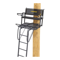
9. With all sections assembled together on ground, secure all sec-
tions together using (8) provided spring lock pins. Handle of
spring lock pin must be put to the outside of ladder side rails.
SEE
FIGURE 6.
Figures
spring lock pins
Figure 6
25
Check for parts online at
www.huntriversedge.com
or call 800-450-EDGE (3343) M-F 8-5