Robotiq Hand-E Gripper Instruction Manual
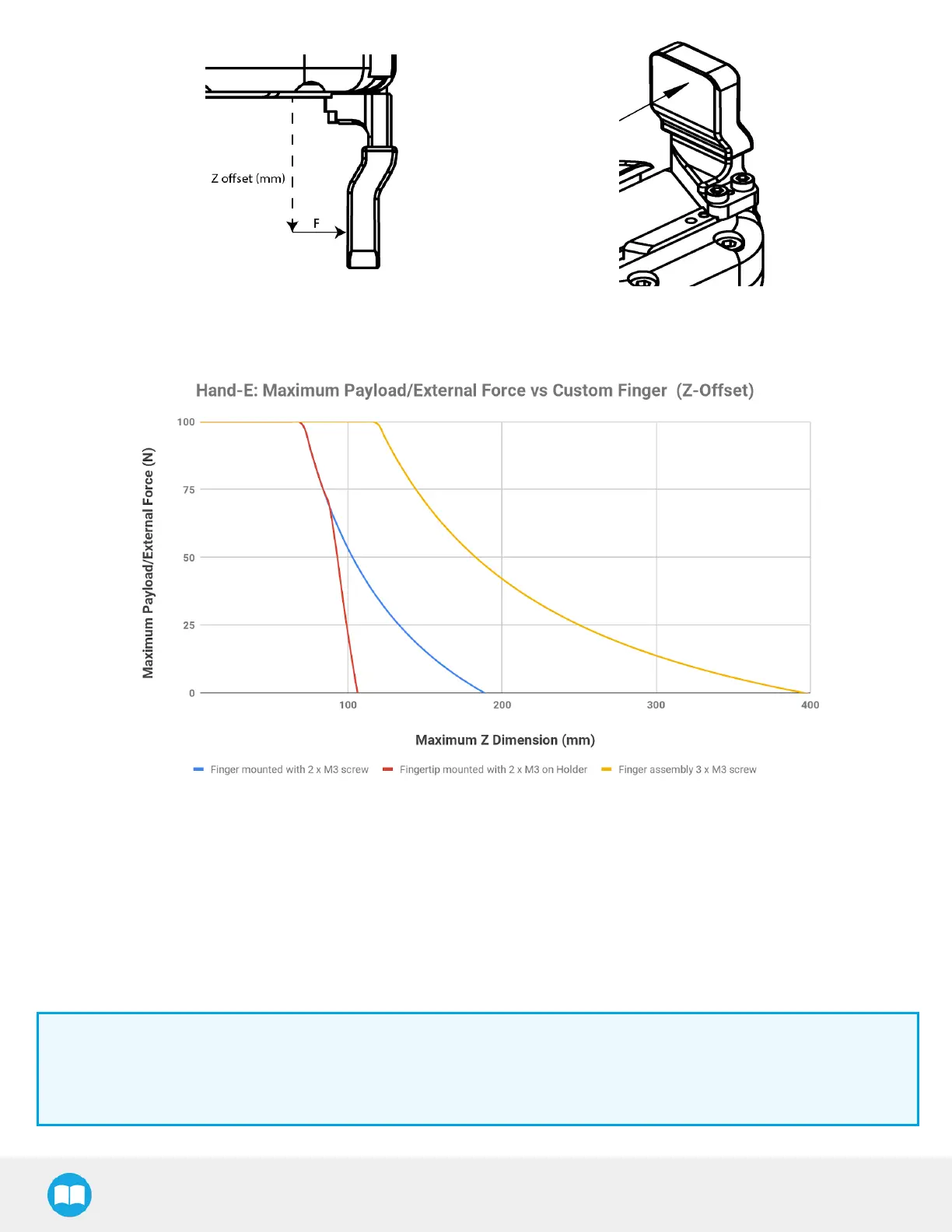
Fig. 5-10: Z-axis offset at which force/payload is applied.
Fig. 5-11: Graph illustrating Maximum Payload/External Force vs. Z-Offset on Custom finger.
l The blue curve in the graph represents the maximum force/payload (F) recommended at given Z offset for a custom finger design
mounted directly on the rack with two (2) M3 screws.
l The red curve in the graph represents the maximum force/payload (F)recommended at given Z offset for a custom finger design
mountend on a fingertip holder with two (2)M3 screws.
l The yellow curve in the graph represents the maximum force/payload (F) recommended at given Z offset for a custom finger design
mounted directly on the rack with three (3) M3 screws.
Info
Data is calculated at the resulting position of the force applied, based on the strength of the M3 screws used. Maximum
grasping force is included in calculations. It represents the maximum force that can be added to the finger (payload force +
external force).
110