29 / 44
4 INSTALLATION
4.1 Lay out
The dimension and weight of ROBOX DV are ndicated in the drawings at page 41, basement has to be flat and level (max 5 mm on 1 m), free
from vibrations and suitable to support the weight of unit, no dynamic loads are involved.
Note : To fix ROBOX DV on metallic frame contact ROBUSCHI or an authorised distributor.
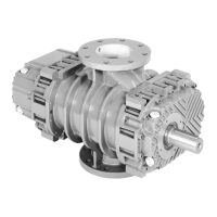
Figure 6 shown the recommended lay-out for one or more ROBOX DV inside a chamber and the dimensions recommended for installation
and for maintenance of ROBOX DV.
It is possible to stay in the maintenance area during ROBOX DV operation.
Warning : Do not stay in the discharge area of relief valve discharge during ROBOX DV operation
The doors or the openings of the ROBOX DV room must be suitable for the passage of the fork lift.
Note : The dimension L must allow the fork lift operation during the on-site positioning of ROBOX DV.
Collettore cumune
Valvola di intercettazione
ROBOX ROBOX ROBOX
Area di manutenzione
1000
1000
1000
20 – 30 L
I E I E I E
Armadi elettrici Carrello elevatore
Fig. 6
4.2 Pipe-lines
Provide terminal pipes of the plant following the dimensions indicated in the drawings at page 41.
Install always a shut-off valve on the terminal pipes of the plant to insulate ROBOX DV from the plant during service operations.
Warning: The surface of dicharge pipes can exceed 70°C
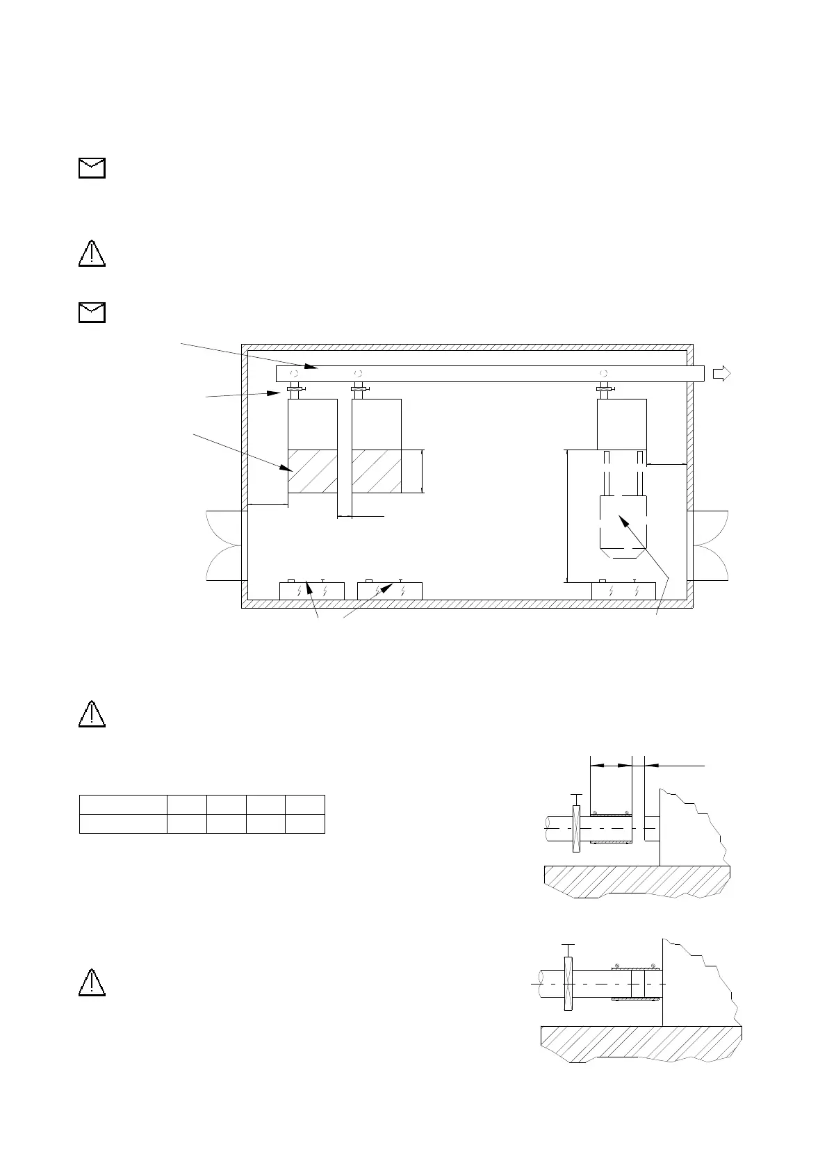
L 20 – 30 mm
Insert the elastic connectors and relevant hose clamps on the terminal pipes as indicated in figure 9.1.
The straight terminal of the pipe must be long L as per table below
ROBOX DV 2 3 4 5
L 200 230 230 300
Position ROBOX DV terminal pipe at the distance indicated in Fig. 7.1
Fig. 7.1
Position the elastic connectors in the final position and fasten the hose clamps Fig. 7.2
Warning : Support pipe-line terminal near elastic connection
The diameter of the discharge manifold must be chosen in order to obtain an average
gas speed < 30 m/s
Fig. 7.2