31 / 44
4.4 Indoor installation
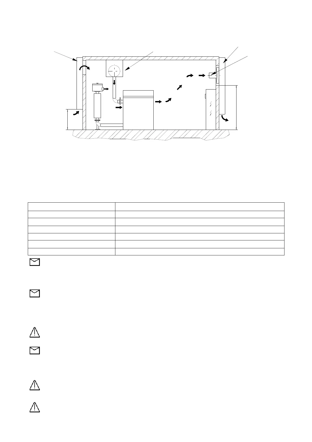
Provide a correct ventilation of the blower room, in the figure 9 below is indicated the flow schema
Inlet silencer Suction manifold Outlet silencer
Fan
ROBOX 2000
Qv
1000 Qv
Fig. 9
It is necessary to provide for the proper ventilation of the room compressors in the absence of which it is not possible to operate the machines,
in particular, include:
- Adequate air inlet openings at the entrance of the flow rate of air Qa sucked by the compressors that work simultaneously and Qv of the flow
of cooling air.
- Suitable exit openings at the outlet of the cooling air flow rate Qv, possibly place an extraction fan of these openings.
Qv (expressed in m³ / h) is the ventilation recommended to maintain the temperature of the room about 10 ° C above the outside temperature,
it can be estimated from the sum No (expressed in kW) of the nominal power of the engines working simultaneously in local compressors with
the following relationship:
Qv = 30 x No
4.5 Outdoor installation
CLIMATIC CONDITIONS MEASURES
Strong sunlight Protect with a canopy
Rainy / Snow Protect with a canopy
Temperature < - 20 °C Use only ROBOX DV and heat inside air before any start-up
Wind > 20 m/s Protect with windbreak walls
Hoarfrost Heat inlet silencer
Dust / Sand storm Special filter with preseparator
Note : For different climatic conditions contact ROBUSCHI ( or an authorised distributor )
4.6 Electrical connections
Electric connections must be set up by authorised specialists in compliance with regulations applying to the place of installation and in
accordance with the requirements of the Body supplying electrical energy.
Note : Robuschi refuses all responsibility for electric connections not complying with the law in force.
Check on the principal motor plate and on the fan motor plate : Voltage, Absorbed current, Frequency, number of phases.
Wiring diagram accompanies the terminal board of the motors , if the diagram has not been supplied request it from the motor manufacturers.
Use suitable electric cables depending on the nominal current of the electric motor.
Keep the electric cables away from heat sources and/or pointed edges
Wire the fan motor to switch-on and switch-off together with blower motor
Warning
: Wire the hoise hood fan motor in order to stop the blower in case the fan motor is faulty or non
functioning
Note : If the ambient temperature is above 30 °C wire the fan motor in order to switch it on togheter with blower
motor and to switch it off with a 15 minutes delay after the blower motor stop.
Protect the motor by means of automatic switch set at the rated value of the motor current .
Install a local control panel with a general switch I (see Fig. 6) with a key in order to lock it in open position during service operations and an
emergency push-button E (see Fig. 6)
Warning
: The emergency push-button E must be easily reached by the operator.
Protect the system by means a suitable grounding device
Warning : Blower service must be carried out after disconnecting the electrical supply.