Roche Diagnostics April 2007
Service manual · Version 2.0 A-19
91xx pH/Electrolyte Analyzers 3 Interface specifications
Interface specifications
Interface specifications
Interface information
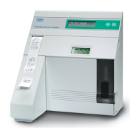
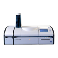
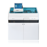
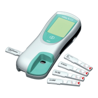
The 9110, 9120, 9130, 9140, 9180 and 9181 analyzers are equipped with a standard
serial interface output. This interface output is intended to be used with standard
commercially available computer systems.
The data transmitted through the serial interface port employs the ASCII code.
The serial interface is terminated on the rear cover with a 9-pin male DB-9 connector.
The signal levels are as follows:
o Binary 1 = -12 V to -3 V
o Binary 0 = +3 V to +12 V
Two stop bits follow the eight data bits to complete the 10 bit word.
The baud rate is set at 9600 Baud fixed.
The maximal recommended cable length is 40 feet.
The pin assignment is as follows:
o pin 1...sample ground...GND
o pin 2...receive data....RxD
o pin 3...send data.......TxD
o pin 4...NC
o pin 5...signal ground...GND
o pin 6...NC
o pin 7...RTS (not used)
o pin 8...CTS(not used)
o pin 9...NC
(NC=Not Connected)
Software
The patient sample data is sent at the end of each measurement, the calibration report
is sent at the end of each calibration.
The interface is always on, independent of the printer settings; the data is always sent.
Higher discharge current
A higher discharge current can be expected when using the serial interface. This must be checked by
suitably qualified personnel, depending on the local regulations.
Note
The arrow up (e.g. out of normal range) is sent as HEX 18 (
↑
), the arrow down as HEX19 (
↓
) and
the ° (degree) is sent as HEX1A (
→
).