Roche Diagnostics April 2007
Service manual · Version 2.0 A-25
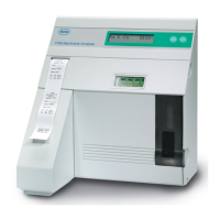
91xx pH/Electrolyte Analyzers 4 Description of modules
Description of modules
Solenoid assembly
Removal of each solenoid is identical. Each solenoid valve has a removable pressure
piece which is held in place by a solenoid cap. To remove the pressure piece, locate the
arrow on the solenoid cap and remove the solenoid cap by sliding it off the solenoid
shaft in the direction of the arrow. This exposes the pressure piece which can now be
removed from the solenoid shaft. To replace pressure piece and cap, energize the
solenoid as described in TEST PINCH VALVES on page B-67. This extends the
solenoid shaft to the outermost position for ease in replacing pressure piece and cap.
Removal of the pressure piece and cap is required prior to removing the solenoid and
allows for easier replacement of the tubing under each solenoid.
To remove the solenoid assembly, the rear panel and the SBC Board (described in
Rear panel assembly on page A-25 and SBC board on page A-26) must be removed
first.
e
For details, see Rear panel assembly on page A-25, SBC board on page A-26.
Each solenoid has an electrical connection to the lamp board which must be
unplugged prior to removal of the solenoid. At this point, remove the two screws on
the front panel to remove the solenoid assembly.
Printer assembly
The printer assembly is designed to allow for easy removal by the user which can be
accomplished without removal of the electrical power to the analyzer. Slide the paper
tray forward to allow access to the printer, tear the paper roll and completely remove
it together with the paper tray. Slide fingers under the printer assembly and pull the
printer forward. This will disengage the printer from the interconnector and enable
removal of the assembly from the front of the analyzer. Removal of the printer should
be performed for replacement and for removal of a paper jam.
To replace the printer, locate the printer slide and insert the printer assembly. Press
firmly into place to ensure electrical connection of the printer.
Rear panel assembly
To remove the rear panel assembly, ensure that the power cord has been disconnected
from the analyzer. Remove the four corner screws to expose the rear panel. The power
supply module located on the rear panel assembly can now be removed by removing
the three screws securing the circuit board and by disconnecting the wiring
Note
The 9110 R-solenoid incorporates two heat sinks and is not interchangeable with the other
solenoids.
Note
Never attempt to dislodge paper from the printer with a paper clip or similar object to avoid
damage to the print head or printer platen.
Due to the update of the 9180 Electrolyte Analyzer according to IVDD compliance a new printer
assembly "PRINTER MODULE, ISE" is available and compatible with 9110 pH Analyzers and
with any 9120, 30, 40, 80 and 81 Electrolyte Analyzer.
e
Further information: see the 91xx Spare Parts List.