Roche Diagnostics April 2007
Service manual · Version 2.0 A-41
91xx pH/Electrolyte Analyzers 5 Electronic diagrams
Electronic diagrams
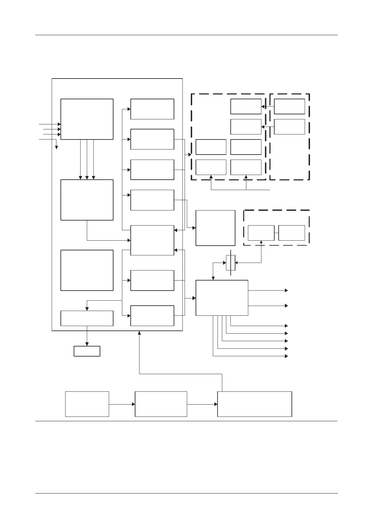
9181 analyzer block diagram
Figure A-6 9181 anayzer block diagram
Preamplifier
Na Amp
K Amp
Cl/Ca/Li Amp
Analog Selector
and
A/D Converter
Power Supply
+22 VDC / +10 VDC
+5 VDC / -5 VDC
+8 VDC / -8 VDC
+22 VDC / +12.5 VDC
Interface Driver
RS232
100 - 240 V~
MAIN
50 - 60 Hz
Fluid Pack Detector
Sensor
Display Driver
Temperature Control
Printer Driver
Microprocessor
Peristaltic Pump Driver
Solenoid Valve Drivers
Power Receptacle
1.6 AT
1.6 AT
Display Module YES/NO Switches
Temp Sensor Sample Sensor
P
r
in
t
e
r
A
sse
m
bl
y
L
a
m
p
B
o
a
r
d
Power Supply Module
Fuse F1 2.5 A/250 V +5 VDC/+24 VDC
+12 VDC/-12 VDC
Na Electrode
K
Cl
Reference
Electrode
GND
S
BC
B
o
a
r
d
D
i
s
pl
ay
B
o
a
r
d
Sample Sensor/Temp Sensor
P. Pump Motor
JP6
Sample Door
JP7
Valve A JP1
Valve B JP2
Valve C JP3
Valve V JP4
Valve R JP5
JP8
JP5
JP1
JP1
JP4
JP2
JP7
JP3
JP1
Needle Sensor
Position Buffer
Needle Motor Driver Probe Motor
Position Sensor
N
ee
dl
e
M
ec
h
a
ni
s
m
A
sse
m
bl
y
JP1 JP1
JP6 JP5
T
u
r
n
t
a
bl
e
A
sse
m
bl
y
Driver BD
Home Sensor
Position Sensor
Bulkhead
BK5013BK5014
JP9
Ctrl Lines
Turntable
Turntable Ctrl Lines
Needle Ctrl Lines