Publication IASIMP-QS003B-EN-P - October 2009 27
Prepare the CompactLogix Hardware Chapter 1
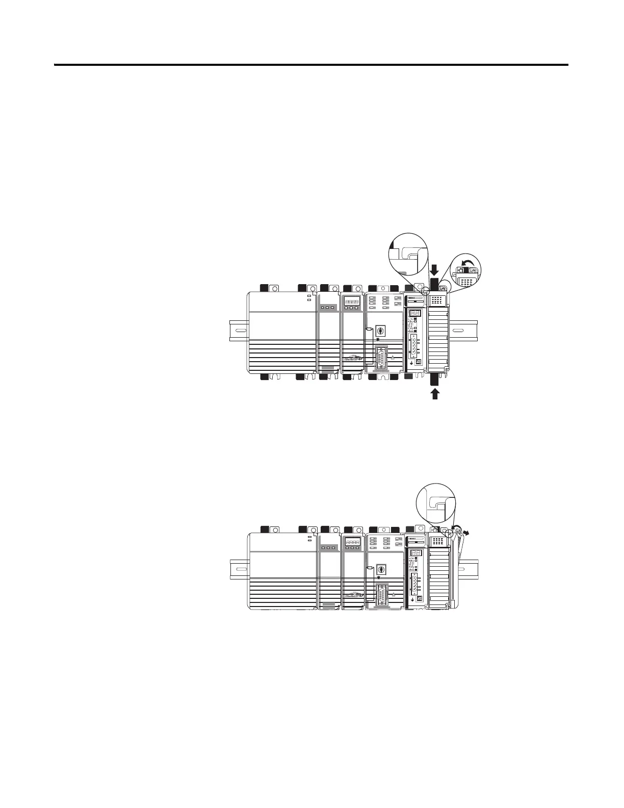
6. Mount the 1769-SDN
and 1769 I/O modules to
the right of the controller
on DIN rail.
In this quick start, the
1769-SDN module is
directly to the right of the
controller in slot 1.
a. Pull locking tabs out.
b. Slide module along
tongue-and-groove
slots on the side of the
controller or modules.
c. Push locking tabs in.
d. Slide white locking tab
to the left.
A maximum of three
modules can be mounted
between the 1769-SDN
and the power supply.
7. Mount the 1769-ECR
end cap terminator.
a. Pull locking tab to the
right.
b. Slide end cap on rail.
c. Pull locking tab to the
left.
 Loading...


