148 Rockwell Automation Publication 1769-UM021I-EN-P - May 2018
Chapter 7 Use I/O Modules with CompactLogix 5370 L1 Controllers
5. Connect the wire that is connected to the - terminal on the external
24V DC power source to the FP- terminal. The FP- terminal is the fifth
terminal from the top on the removable connector.
6. Plug the removable connector into the controller.
7. Secure the removable connector in place.
8. Turn on power to the separate external 24V DC power source
connected to the removable connector.
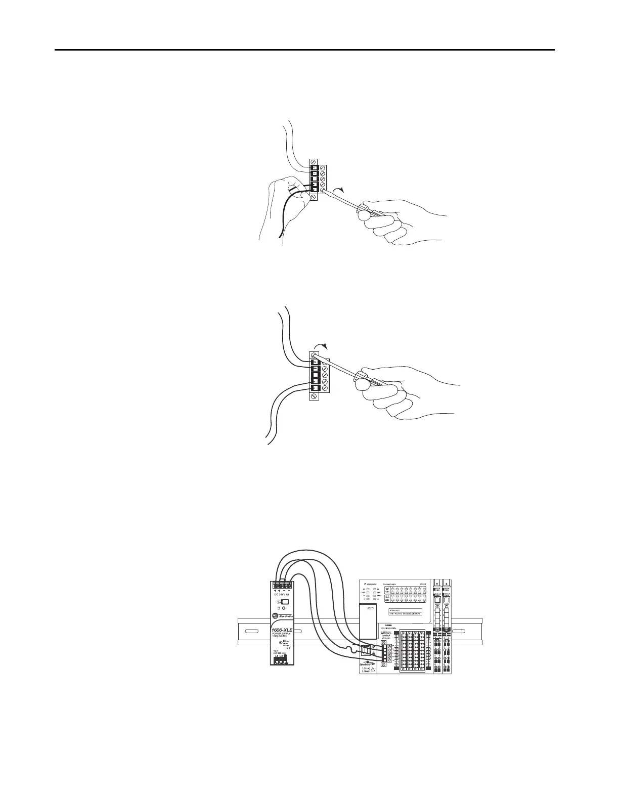
The following graphic shows separate external 24V DC power supply that is
connected to the VDC+/VDC- and FP+/FP- terminals on the removable
connector, respectively.
IMPORTANT: No wires are
connected to the NC terminal.
 Loading...


