204 Rockwell Automation Publication 1769-UM021I-EN-P - May 2018
Chapter 8 Use I/O Modules with CompactLogix 5370 L2 Controllers
Output Array
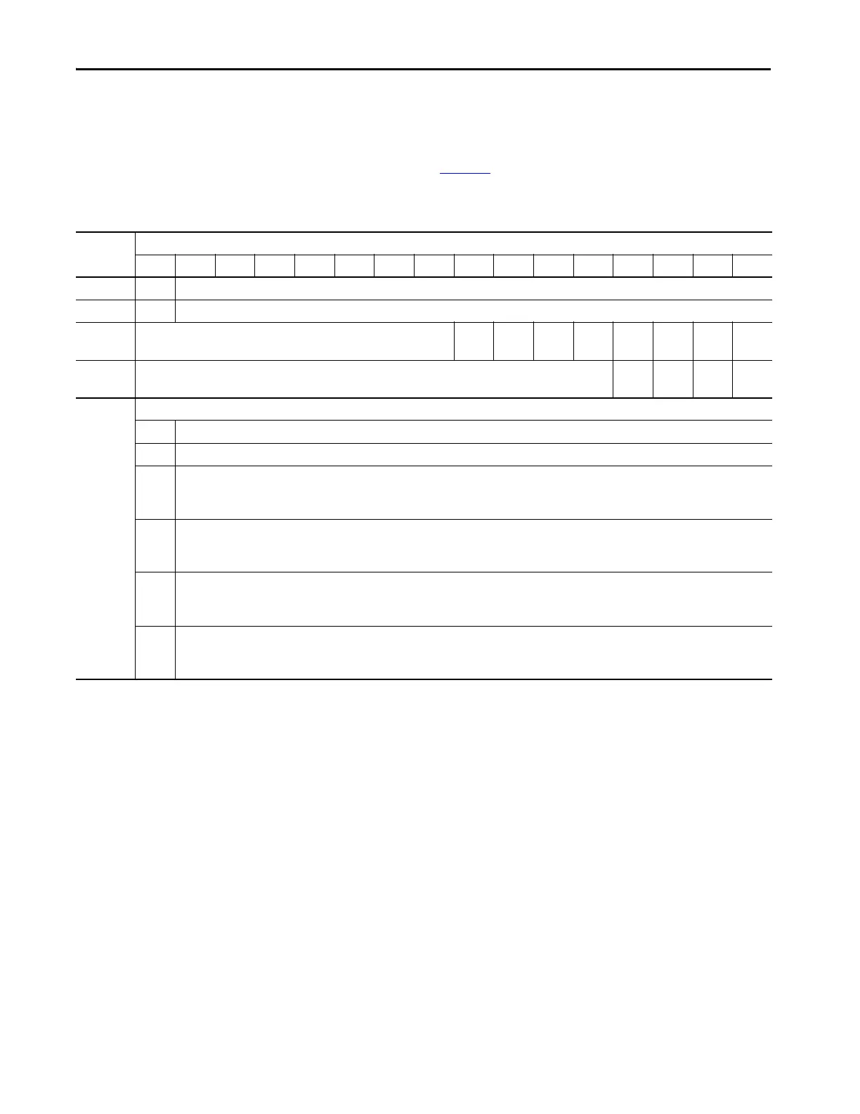
The embedded analog I/O output image array of the module contains four
words as described in Tab le 18
. This array is write only and the default value for
all bits is 0.
Table 18 - CompactLogix 5370 L2 Controller Embedded Analog I/O Module Output Data Array
Word
Bit
1514131211109876543210
0 S Analog Output Data Value Channel 0
1 S Analog Output Data Value Channel 1
2NuCL
I3
CH
I3
CL
I2
CH
I2
CL
I1
CH
I1
CL
I0
CH
I0
3NuCL
O1
CH
O1
CL
O0
CH
O0
Where: Analog Output Data Value Channel x is the data written to the channel.
SSign bit
Nu Bit not used
CH
Ix
Use this bit to cancel High Process Alarm Latch functionality for an input.
0 = Do not cancel
1 = Cancel the alarm latch
CL
Ix
Use this bit to cancel Low Process Alarm Latch functionality for an input.
0 = Do not cancel
1 = Cancel the alarm latch
CH
Ox
Use this bit to cancel High Process Alarm Latch functionality for an output.
0 = Do not cancel
1 = Cancel the alarm latch
CL
Ox
Use this bit to cancel Low Process Alarm Latch functionality for an output.
0 = Do not cancel
1 = Cancel the alarm latch
 Loading...


