78 Rockwell Automation Publication 1769-UM021I-EN-P - May 2018
Chapter 4 Install the CompactLogix 5370 L3 Controller
Wire Size and Terminal Screw Torque
Each terminal accepts one or two wires with the following restrictions.
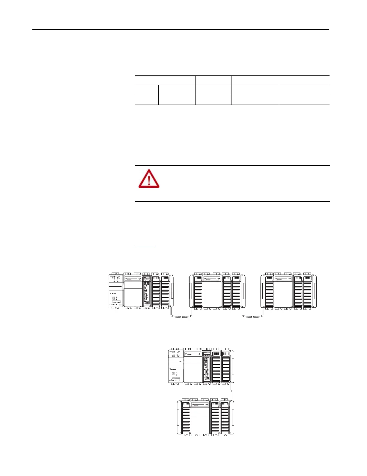
Mount the System
You can mount a CompactLogix 5370 L3 control system on a DIN rail or on
apanel.
A CompactLogix 5370 L3 control system must be mounted so that the
modules are horizontal to each other. If you separate modules into multiple
banks, the banks can be vertical or horizontal to each other.
Figure 6
shows example systems with local expansion modules included.
Figure 6 - Example CompactLogix 5370 L3 Control Systems
Wire Type Wire Size Terminal Screw Torque Retaining Screw Torque
Solid Cu-90 °C (194 °F) #14…#22 AWG 0.68 N•m (6 lb•in) 0.46 N•m (4.1 lb•in)
Stranded Cu-90 °C (194 °F) #16…#22 AWG 0.68 N•m (6 lb•in) 0.46 N•m (4.1 lb•in)
ATTENTION: During panel or DIN rail mounting of all devices, be sure that
all debris (such as metal chips or wire strands) is kept from falling into the
controller. Debris that falls into the controller could cause damage while
the controller is energized.
1769-CRLx Cable
Horizontal Orientation
Vertical Orientation
Bank 1 Bank 2
Bank 1
Bank 2
Bank 3
1769-CRLx Cable
1769-CRRx Cable
 Loading...


