Rockwell Automation Publication 1769-UM021I-EN-P - May 2018 33
Install the CompactLogix 5370 L1 Controller Chapter 2
You can mount the CompactLogix 5370 L1 controller on the following
DIN rails:
• EN 50 022 - 35 x 7.5 mm (1.38 x 0.30 in.)
• EN 50 022 - 35 x 15 mm (1.38 x 0.59 in.)
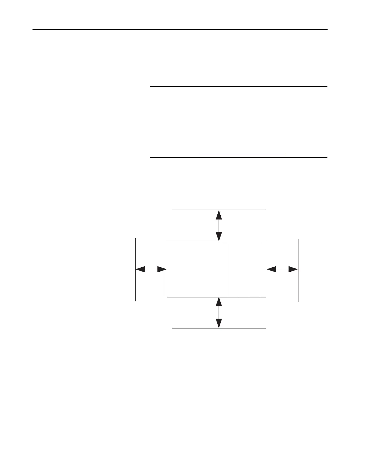
Minimum Spacing
Maintain spacing from enclosure walls, wireways, and adjacent equipment.
Allow 50 mm (2 in.) of space on all sides, as shown. This spacing provides
ventilation and electrical isolation.
IMPORTANT You must install bumpers on the back of your CompactLogix 5370 L1
controller before mounting it on the EN 50022 - 35 x 15 mm
(1.38 x 0.59 in.) DIN rail.
Bumper Selection:
• For more information on Bumper Selection, see Rockwell
Automation® Knowledgebase article #591565. You can access
the article at: (Login required)
https://rockwellautomation.custhelp.com/
Bottom
Top
CompactLogix 5370 L1
Controller with
Embedded Power
Supply and I/O Module
End Cap
50 mm
(2 in.)
50 mm
(2 in.)
50 mm
(2 in.)
50 mm
(2 in.)
Side Side
1734 POINT I/O Module
1734 POINT I/O Module
1734 POINT I/O Module
 Loading...


