144 Rockwell Automation Publication 2198-UM001D-EN-P - May 2014
Chapter 7 Troubleshooting the Kinetix 5500 Drive System
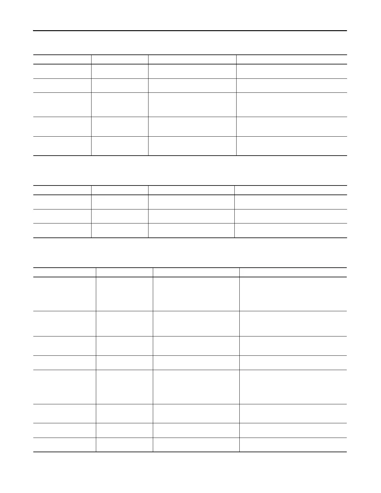
Table 58 - INIT FLT Fault Codes
Exception Code on Display Exception Text Problem Possible Solutions
INIT FLT M01 – ENCODER DATA Smart Encoder Data Corruption The data stored in the encoder has a checksum error.
•Cycle control power
• Return motor for repair if fault continues
INIT FLT M02 – MTR DATA RANGE Motor Data Range Error
A motor data attribute stored in the encoder is out of
range.
•Cycle control power
• Return motor for repair if fault continues
INIT FLT M03 – MTR ENC STARTUP
Motor Feedback Communication
Startup
Communication with the encoder could not be
established.
•Cycle control power
• Check motor feedback connector
• Check motor power and feedback shield terminations on the drive
• Return motor for repair if fault continues
INIT FLT M14 – SAFETY FIRMWARE Safety Firmware
The loaded Safety firmware is not compatible with the
drive firmware.
•Cycle control power
• Update the drive firmware
• Return drive for repair if fault continues
INIT FLT M20 – UNKNOWN
MODULE
Unknown Module The product code of the power board is invalid.
•Cycle control power
• Reset the drive
• Return drive for repair if fault continues
Table 59 - INHIBIT Fault Codes
Exception Code on Display Exception Text Problem Possible Solutions
INHIBIT S02 – MOTOR NOT
CONFIGURED
Motor Not Configured The motor has not been properly configured for use. Verify motor configuration in the Logix Designer application.
INHIBIT S03 – FEEDBACK NOT
CONFIGURED
Feedback Not Configured
The feedback has not been properly configured for
use.
Verify feedback configuration in the Logix Designer application.
INHIBIT M05 – SAFE TORQUE OFF Start Inhibit – Safe Torque Off The safety function has disabled the power structure.
• Check safety input wiring
•Check state of safety devices
Table 60 - NODE FLT Fault Codes
Exception Code on Display Exception Text Problem Possible Solutions
NODE FLT 01 – LATE CTRL UPDATE Control Connection Update Fault
Several consecutive updates from the controller have
been lost.
• Remove unnecessary network devices from the motion network
• Change network topology so that fewer devices share common
paths
• Use high performance network equipment
• Use shielded cables
• Separate signal wiring from power wiring
NODE FLT 02 – PROC WATCHDOG nn Processor Watchdog Fault
The processor on the power board or control board
failed to update in a certain amount of time.
The nn sub-codes 00…06 are internal and result in
the same possible solution.
• Cycle control power
• Update the drive firmware
• Return drive for repair if fault continues
NODE FLT 03 – HARDWARE 00 Hardware Fault -PwrIF
Communication with the power board could not be
established.
• Cycle control power
• Update the drive firmware
• Return drive for repair if fault continues
NODE FLT 03 – HARDWARE 01 Hardware Fault - Power Board DSP chip on the power board failure.
• Cycle control power
• Return motor for repair if fault continues
NODE FLT 03 – HARDWARE 02 Hardware Fault - DSL
Communication with the encoder could not be
established.
• DSL feedback wiring is incorrect (check against wiring diagram)
• DSL feedback wiring is shorted or open
• DSL feedback cable is defective
• Kinetix VP motor feedback device is defective
•Cycle power
• Return drive for repair if fault continues
NODE FLT 03 – HARDWARE 03 DSL Internal Hardware Fault
A DSL hardware error internal to the drive was
detected.
• Check DSL feedback device, wiring, and cable
•Cycle power
• Return drive for repair if fault continues
NODE FLT 03 – HARDWARE 04
Hardware Fault - Board
Compatibility
The control and power boards are incompatible. Return drive for repair if fault continues
NODE FLT 05 – CLOCK SKEW FLT Clock Skew Fault
The controller time and the drive's system time are
not the same.
• Cycle control power
• Check controller and Ethernet switch operation

 Loading...


