Rockwell Automation Publication 2198-UM001D-EN-P - May 2014 51
Mounting the Kinetix 5500 Drive System Chapter 3
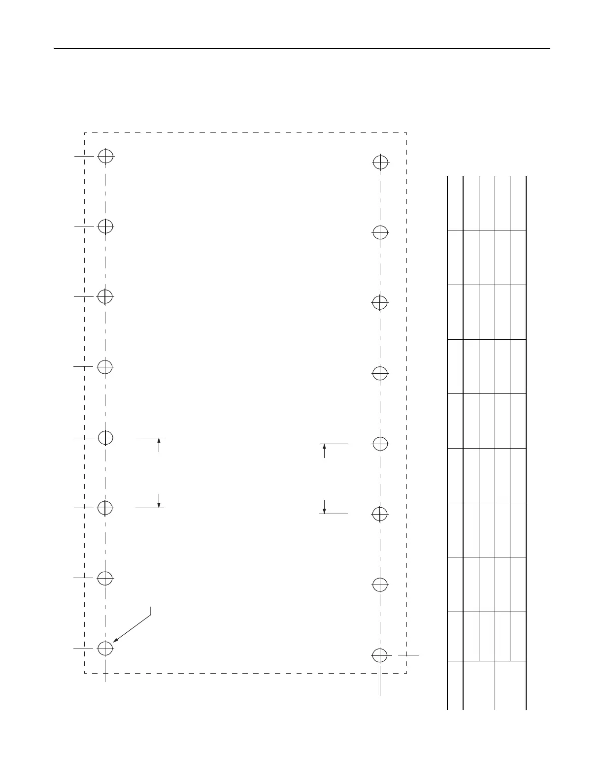
These hole patterns apply when all drives in the system are frame 1 or frame 2.
There is 50 mm (2.0 in.) between mounting holes (A-to-A and B-to-B).
Figure 23 - Frame 1 and Frame 2 Hole Patterns
16x
ØM4 (#8-32)
Axis 1
Axis 3
Frame 1
193.68
(7.6)
Frame 2
243.84
(9.6)
Axis 4
Axis 5
Axis 6
Axis 7
Axis 8
Axis 2
A
B
A
B
A
B
A
B
A
B
A
B
A
B
A
B
0
0
50.0 (2.0)
50.0 (2.0)
Frame Size Dimension Axis 1 Axis 2 Axis 3 Axis 4 Axis 5 Axis 6 Axis 7 Axis 8
1
A 4.51 (0.2) 54.51 (2.1) 104.51 (4.1) 154.51 (6.1) 204.51 (8.1) 254.51 (10.0) 304.51 (12.0) 354.51 (14.0)
B 0 50.0 (2.0) 100.0 (3.9) 150.0 (5.9) 200.0 (7.9) 250.0 (9.8) 300.0 (11.8) 350.0 (13.8)
2
A 5.00 (0.2) 60.0 (2.4) 115.0 (4.5) 170.0 (6.7) 225.0 (8.9) 280.0 (11.0) 335.0 (13.2) 390.0 (15.4)
B 0 55.0 (2.2) 110.0 (4.3) 165.0 (6.5) 220.0 (8.7) 275.0 (10.8) 330.0 (13.0) 385.0 (15.2)
Dimensions are in mm (in.)

 Loading...


