Rockwell Automation Publication 2198-UM001D-EN-P - May 2014 53
Mounting the Kinetix 5500 Drive System Chapter 3
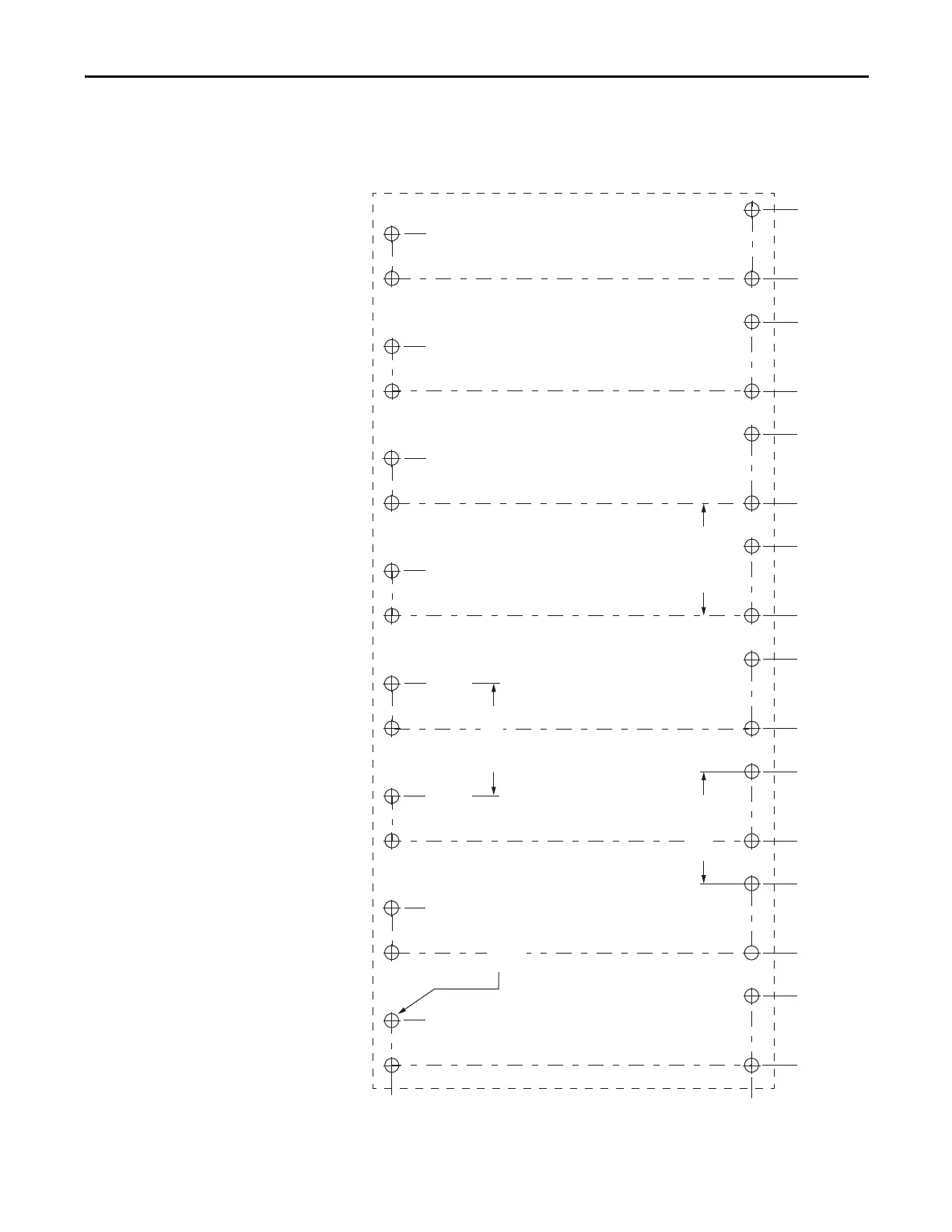
This hole pattern applies when all drives in the system are frame 3 drives. There is
85.20 mm (3.4 in.) between mounting holes, as shown.
Figure 25 - Frame 3 Hole Pattern
273.70
(10.8)
0
52.50
(2.1)
85.20
(3.4)
137.70
(5.4)
0
170.40
(6.7)
222.90
(8.8)
255.60
(10.1)
308.10
(12.1)
340.80
(13.4)
393.30
(15.5)
426.0
(16.8)
478.50
(18.8)
511.20
(20.1)
563.70
(22.2)
596.40
(23.5)
648.90
(25.5)
Axis 1 Axis 2 Axis 3 Axis 4
Axis 5 Axis 6 Axis 7 Axis 8
32x
ØM4 (#8-32)
34.00
(1.3)
119.20
(4.7)
204.40
(8.0)
289.60
(11.4)
374.80
(14.8)
460.0
(18.1)
545.20
(21.5)
630.40
(24.8)
85.20 (3.4)
85.20 (3.4)
85.20 (3.4)
Dimensions are in
mm (in.)

 Loading...


