EasyManuals Logo

Rockwell Automation Allen-Bradley Kinetix 5500 Series User Manual

Rockwell Automation Allen-Bradley Kinetix 5500 Series
244 pages
To Next Page IconTo Next Page
To Previous Page IconTo Previous Page
Page #54 background imageLoading...
Page #54 background image
54 Rockwell Automation Publication 2198-UM001D-EN-P - May 2014
Chapter 3 Mounting the Kinetix 5500 Drive System
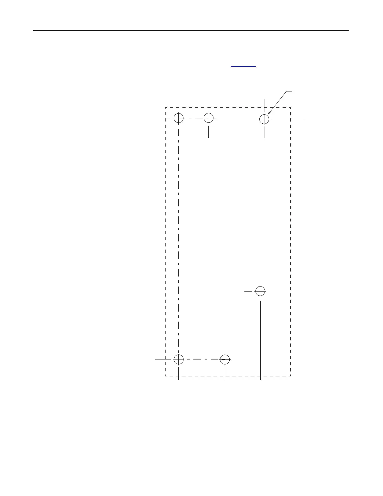
This hole pattern applies when transitioning from frame 3 drives to frame 1
drives. To mount additional frame 1 drives to the right of Axis 2 in this figure,
refer to the frame 1 hole pattern in Figure 23
.
Figure 26 - Frame 3 to Frame 1 Hole Pattern
273.70
(10.8)
0
52.50
(2.1)
0
6x
ØM4 (#8-32)
Axis 1
(frame 3)
Axis 2
(frame 1)
272.23
(10.7)
78.55
(3.1)
92.70
(3.7)
97.20
(3.8)
34.00
(1.3)
Dimensions are in mm (in.)

Table of Contents

Questions and Answers:

Question and Answer IconNeed help?

Do you have a question about the Rockwell Automation Allen-Bradley Kinetix 5500 Series and is the answer not in the manual?

Rockwell Automation Allen-Bradley Kinetix 5500 Series Specifications

General IconGeneral
BrandRockwell Automation
ModelAllen-Bradley Kinetix 5500 Series
CategoryServo Drives
LanguageEnglish

Related product manuals