PowerFlex 700S
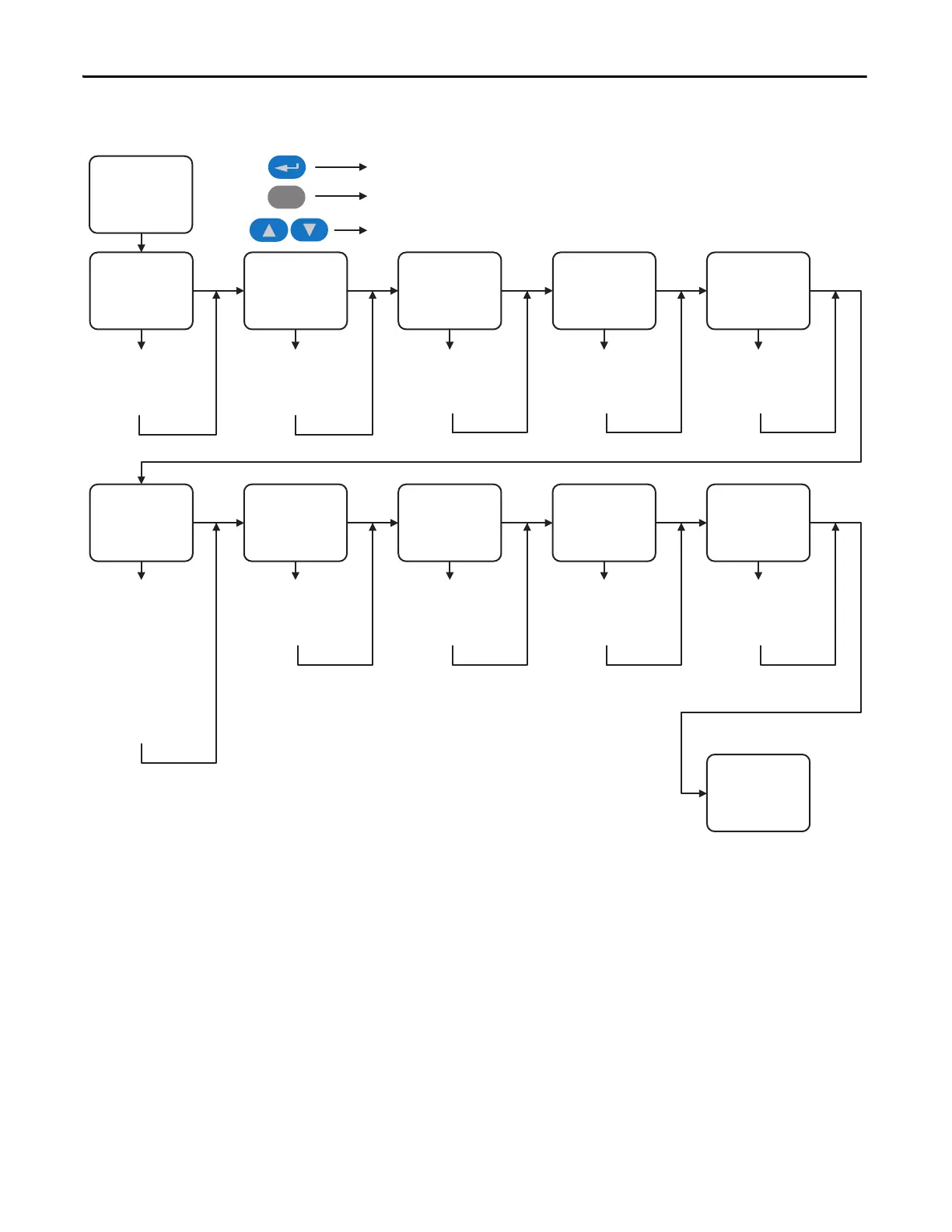
Start-Up
Motor Control Motor Data
Feedback
Configuration
Power Circuit
Test
Direction Test
Motor Tests Inertia Measure Speed Limits Speed Control Start / Stop / I/O
Select:
Motor Control Mode,
DB Resistor
Enter:
Motor NP Data,
Power & Units, FLA,
Volts, Hertz, RPM, Poles
Setup / Select:
Encoder, Resolver,
Hi-Res Encoder,
Linear Sensor
Diagnostic Check for:
Drive Power Circuit
Verify Direction
Field Oriented Control:
Measure: Stator
Resistance, Leakage
Inductance, Magnetizing
Inductance,
Slip Frequency
PMag Motor:
Measure: Encoder Offset,
Stator Resistance, Stator
Inductance, Back EMF
Measure:
System Inertia
Setup / Select:
Direction Control,
FWD, REV and
Absolute Speed Limits
Select:
Speed Reference
Sources
Done / Exit
Esc
Select a menu option or move down one level
Go back one selection or one level
Scroll through all choices
Configure: Digital Inputs,
Digital Outputs, Analog
Inputs, Analog Outputs
 Loading...


