172 Rockwell Automation Publication 20D-PM001D-EN-P - March 2019
Appendix C Control Block Diagrams
Diagram Conventions and
Definitions
Definitions of the Per Unit system
:
1.0 PU Position = Distance traveled / 1 sec at Base Spd
1.0 PU Speed = Base Speed of the Motor
1.0 PU Torque = Base Torque of the Motor
Task 1
Task 3
Task 2
0 .5 mS
8 .0 mS
2 .0 mS
0 .5 mS
1 .0 mS
0 .25 mS
1 .0 mS
8 .0 mS 8 .0 mS
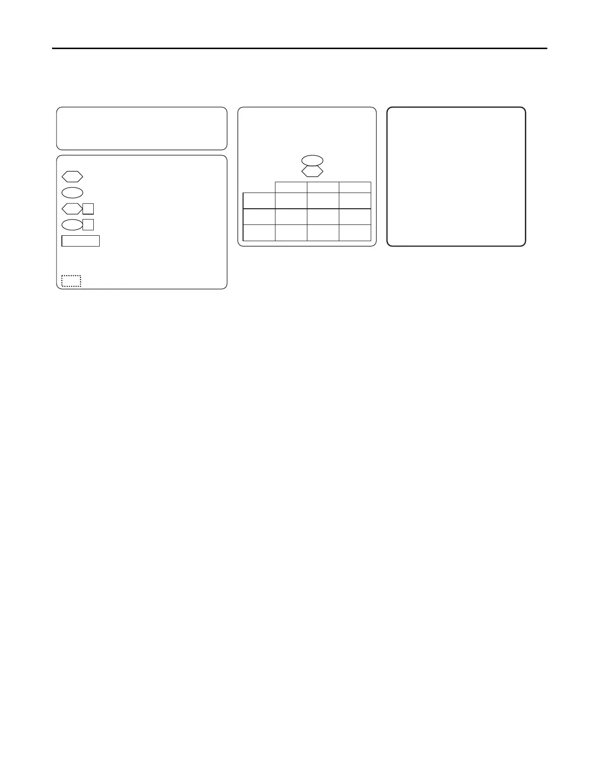
148FW TaskTime Actl
val = 0 val = 2val = 1
FW TaskTime Sel 146
Processor Task time selection:
.
NOTE: Faster Task time selections may require
program functions to be disabled to stay within
processor load capabilities.
( ) = Enumerated Parameter
[ ] = Page and Coordinate
ex. 3A2 = pg 3, Column A, Row 2
= Constant value
Read Only Parameter with Bit Enumeration
Read / Write Parameter with Bit Enumeration
Provides additional information
Read Only Parameter
Read / Write Parameter
Symbols
:
* Notes, Important :
(1) Parameter 147 [FW Functions EN] is used to
activate and deactivate firmware functions. The
PowerFlex 700S drives ships with the position
regulator deactivated. To enable the position
regulator, set Parameter 147, bit 16 to 1 “On”.
(2) Parameter 1000 [UserFunct Enable] is used to
activate and deactivate the User Functions.
(3) These diagrams are for reference only and may
not accurately reflect all logical control signals;
actual functionality is implied by the
approximated diagrams. Accuracy of these
diagrams is not guaranteed.
 Loading...


