Rockwell Automation Publication 20D-PM001D-EN-P - March 2019 191
Control Block Diagrams Appendix C
1
2
3
4
5
6
BA
D
C
FE HG
I
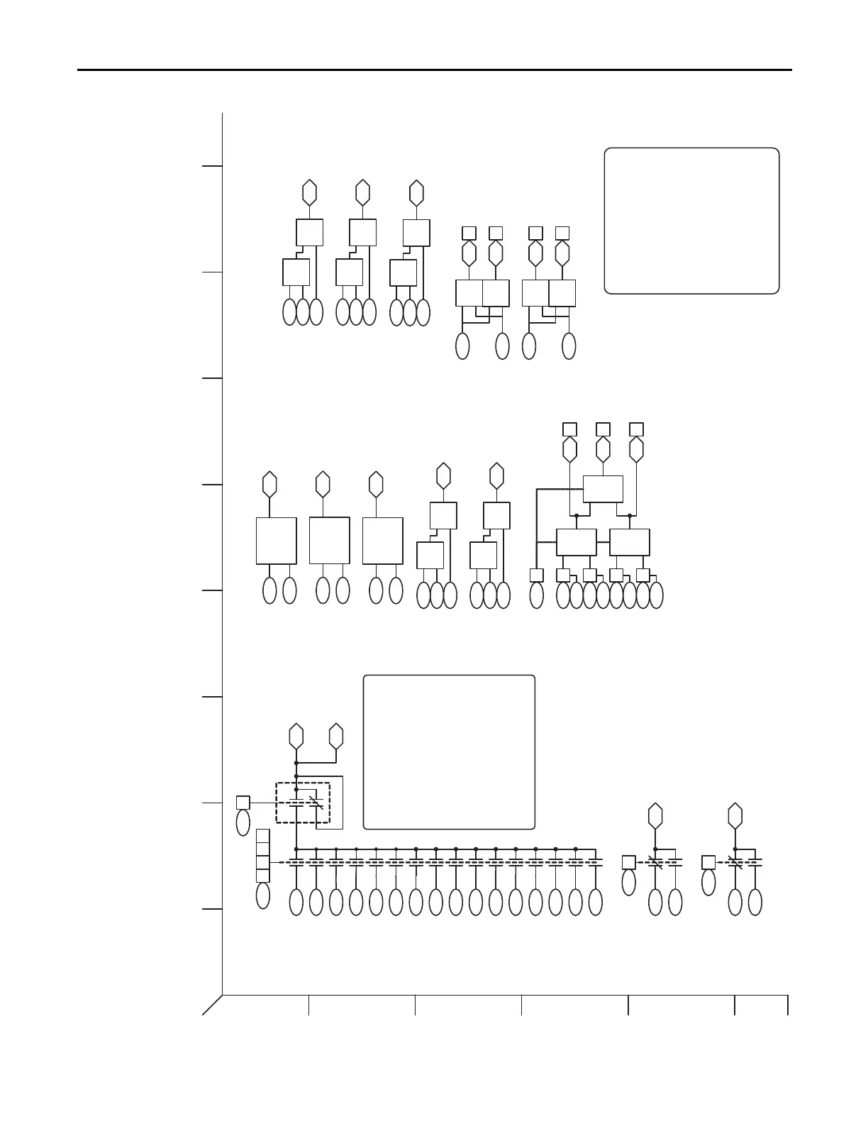
User Functions
(Task 3)
Convert
DInt-Real
x Scale
10491047
1048
Convert
Real-DInt
x Scale
10521050
1051
<
=
>
=
1071
1072
1062 04
1062 05
<
=
>
=
1073
1074
1062 06
1062 07
Compare 1A
Compare 1B
Compare 2A
Compare 2B
(Cmpr 1 A>/=B)
(Cmpr 2 A</=B)
(Cmpr 2 A>/=B)
(Cmpr 1 A</=B)
X
/
MulDiv 1 Input 1053
1054
1055
1056
MulDiv 1 Mul
MulDiv 1 Div
MulDiv 1 Result
X
/
MulDiv 2 Input 1057
1058
1059
1060
MulDiv 2 Mul
MulDiv 2 Div
MulDiv 2 Result
DInt2Real1 In
DInt2Rea1l Scale
Real2DInt In
Real2DInt Scale
DInt2Real1 Result
Real2DInt Result
Logic/Cmpr State
Logic/Cmpr State
1027
1026
1022 06
1028
Sel Switch Ctrl
(SW DInt 1 On)
SW DInt 1 NO
SW DInt 1 NC
SW DInt 1 Output
0
1
1024
1023
1022 05
1025
Sel Switch Ctrl
(SW Real 1 On)
SW Real 1 NO
SW Real 1 NC
SW Real 1 Output
0
1
And,
Nand,
Or, Nor,
Xor,
Nxor
And,
Nand,
Or, Nor,
Xor,
Nxor
And,
Nand,
Or, Nor,
Xor,
Nxor
1062 00
1062 02
1062 01
1063
1065
1067
1069
Logic 1A Data
Logic 1B Data
Logic 2A Data
Logic 2B Data
1064
1066
1068
1070
Logic 1A Bit
Logic 1B Bit
Logic 2A Bit
Logic 2B Bit
Logic/Cmpr State
(Logic 1 Result )
(Logic 3 Result )
(Logic 2 Result )
1061 xxLogic Config
1029
1030
1031
0
1
2
3
4
5
6
1032
1034
1035
SelSwtch In 01
(Real)
7
8
9
10
1036
1037
1038
1039
1040
12
13
14
15
11
1022 01 02 03 04
1033
1041
1042
1043
1044
1045
1046
SelSwtch DIntOut
(Integer)
SelSwtch RealOut
(Real)
SelSwtch In 02
(Real)
SelSwtch In 03
(Real)
SelSwtch In 04
(Real)
SelSwtch In 05
(Real)
SelSwtch In 06
(Real)
SelSwtch In 07
(Real)
SelSwtch In 08
(Real)
SelSwtch In 09
(Real)
SelSwtch In 10
(Real)
SelSwtch In 11
(Real)
SelSwtch In 12
(Real)
SelSwtch In 13
(Rea
l)
SelSwtch In 14
(Real)
SelSwtch In 15
(Real)
SelSwtch In 00
(Real)
with Rounding
1022 00
Sel Swtch Ctrl
Sel Swtch Ctrl
User Functions - Execution order
1) Selector Switch Function (16 input)
2) Real SPDT Selector switch (2 input)
3) DInt SPDT Selector switch (2 input)
4) Logic Function
5) Comparator 1
6) Comparator 2
7) Data Conversion 1 DInt to Real
8) Data Conversion 2 Dint to Real
9) Data Conversion Real to DInt
10) Multiply/Divide Function 1
11) Multiply/Divide Function 2
12) MOP Function
13) Add/Subtrct Function 1
14) Add/Subtrct Function 2
15) Add/Subtrct Function 3
16) Timer 1
17) Timer 2
+
-
AddSub 1 Input 1096
1097
1098
1099
AddSub 1 Add
AddSub 1 Subtrct
AddSub 1 Result
+
-
AddSub 2 Input 1100
1101
1102
1103
AddSub 2 Add
AddSub 2 Subtrct
AddSub 2 Result
+
-
AddSub 3 Input 1104
1105
1106
1107
AddSub 3 Add
AddSub 3 Subtrct
AddSub 3 Result
Convert
Dint-Real
x Scale
11521150
1151
DInt2Real2 In
DInt2Real2 Scale
DInt2Real2 Result
**
Selector Switch can be controlled via
the Digital Inputs or Parameter
1022.Use “UserGen Selx” as the
Digital input type. The Digital input
selection is an “OR” function with
Parmeter 1022.
Selector Switch Control Table
Digital In P 1022
UserGen Sel0 OR P1022 Bit 1
UserGen Sel1 OR P1022 Bit 2
UserGen Sel2 OR P1022 Bit 3
UserGen Sel3 OR P1022 Bit 4
 Loading...


