Rockwell Automation Publication 750-QS100B-EN-P - August 2020 9
Step 1: Gather the Required Information
Record Velocity Reference and Start/Stop Sources
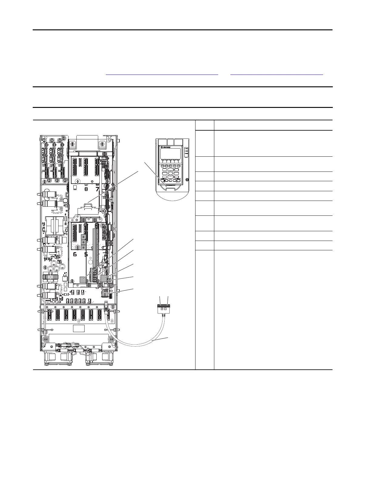
Use this diagram to help determine where signal and control sources are connected in each of your drives. You need this
information when you get to Step 8: Set Up Velocity Reference on page 44
and Step 9: Set Up Start/Stop on page 46.
IMPORTANT PowerFlex® 755T products use the term ‘port’ to designate (in firmware and software) the physical location where hardware is
located to make it easier to select hardware or functions to program.
Figure 1 - Basic Subset of Signal Source and Port Locations
Items Descriptions
1 Port 1 connection on the drive-mounted Human Interface Module
(HIM) (The drive-mounted HIM is shown not installed. When it is
installed, the drive-mounted HIM is mounted to the HIM cradle,
connecting at item 2.)
2 Port 1 connection on the HIM cradle (where the drive-mounted HIM
is installed and item 1 connects)
3 Communication option module (shown installed at port 5)
4 Expansion I/O module (shown installed at port 4)
5 Embedded EtherNet/IP™ connectors
6 Terminal block TB1 behind port 0 (the EtherNet/IP port) on the main
control board
7 Port 2 for handheld HIM connection, remote HIM connection, or a
splitter cable (item 10)
8 Splitter cable connection to port 2
9 Splitter cable connection to port 3
10 Splitter cable that connects to port 2 (item 7) and provides a port 2
splitter cable connection (item 8) and port 3 splitter cable
connection (item 9)
3
4
Sh
Sh
PTC–
PTC+
Ao0–
Ao0+
Ao1–
Ao1+
–10V
10VC
+10V
Ai0–
Ai0+
Ai1–
Ai1+
24VC
+24V
DiC
Di0
Di1
Di2
Di3
Di4
Di5
7
55
66
1
2
1010
89

 Loading...


