118 Rockwell Automation Publication 750-IN118A-EN-P - May 2021
Chapter 5 Service and Maintenance
1. Review Product Advisories on page 11.
2. Remove power from the system. See Remove Power from the System on
page 117.
3. Open the bay door and disconnect the power connection from the fan
(item 3 in Figure 100
).
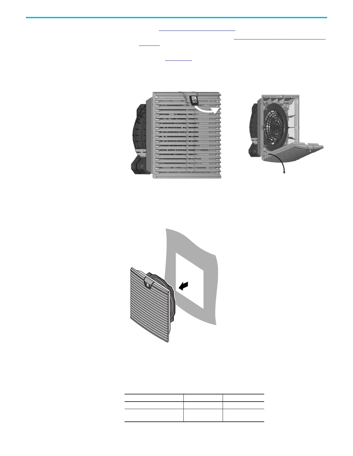
4. Lift the tab on the top center of the vent cover and open the vent cover.
5. Remove the screws that secure the filter housing to the bay door. These
screws are at the corners of the filter housing.
6. Remove the fan/vent assembly through the cutout in the bay door.
Figure 103 - Removing the Fan/Vent Assembly
7. Insert the new fan/vent assembly, making sure that the airflow direction
is into the bay. The direction of airflow and the direction of rotation are
each marked on the fan housing with an arrow.
8. Install the screws that secure the vent to the bay door.
Figure 101 - Lifting the Vent Cover Tab Figure 102 - Opening the Vent Cover to
Access the Mounting Screws
Table 23 - Torques for Screws that Attach the Vent to the Bay Door or Exhaust Hood
Rittal Part Number of Vent Screw Diameter Torque
3238200 3.5 mm (0.13 in) 2.3 N•m (20 lb•in)
3240200, 3241110, 3243200,
3245510
4.5 mm (0.18 in) 3.4 N•m (30 lb•in)

 Loading...


