EasyManuals Logo

Rockwell Automation Allen-Bradley PowerFlex 755T Installation Instructions

Rockwell Automation Allen-Bradley PowerFlex 755T
130 pages
To Next Page IconTo Next Page
To Previous Page IconTo Previous Page
Page #47 background imageLoading...
Page #47 background image
Rockwell Automation Publication 750-IN118A-EN-P - May 2021 47
Chapter 3 Mechanical and Electrical Installation
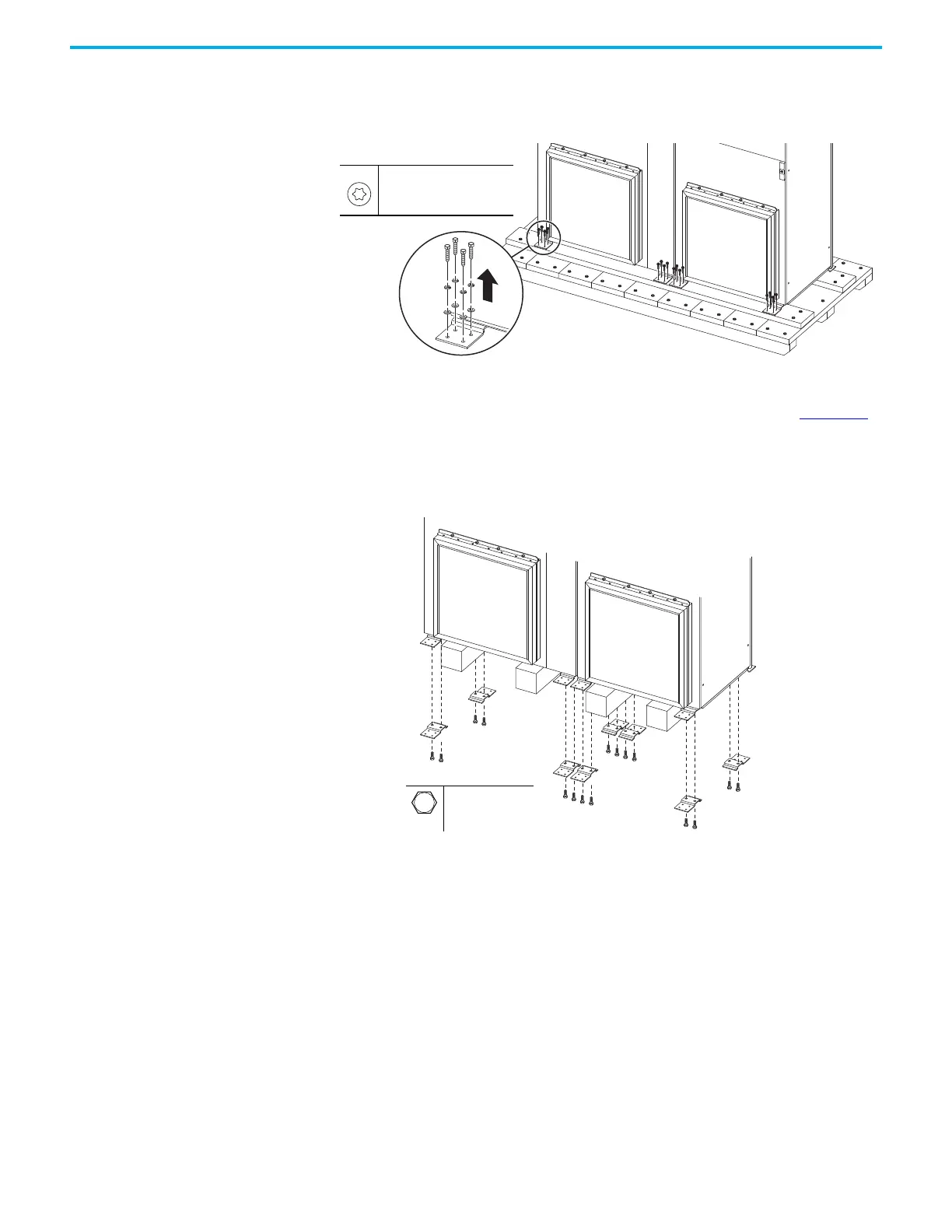
Remove Shipping Skid and
Cleats
1. With the bay standing on the shipping skid, remove the bolts that attach
the bay cleats to the shipping skid.
Figure 43 - Detaching the Bay Cleats from the Shipping Skid
2. For this step, see the Transport by Crane or Hoist procedure in the
PowerFlex 755T Drives Configured to Order Program Receiving,
Handling, and Storage Installation Instructions, publication 750-IN110.
Place the bay on supports that provide enough space under the cleats to
remove the cleats from the bay. Wooden beams can be used as supports.
3. Remove the cleats from the bay.
Figure 44 - Removing the Cleats
3/8 in X 3-1/8 in lag screw
T30
M12
19 mm

Table of Contents

Other manuals for Rockwell Automation Allen-Bradley PowerFlex 755T

Questions and Answers:

Question and Answer IconNeed help?

Do you have a question about the Rockwell Automation Allen-Bradley PowerFlex 755T and is the answer not in the manual?

Rockwell Automation Allen-Bradley PowerFlex 755T Specifications

General IconGeneral
BrandRockwell Automation
ModelAllen-Bradley PowerFlex 755T
CategoryDC Drives
LanguageEnglish

Related product manuals