Rockwell Automation Publication 750-IN118A-EN-P - May 2021 117
Chapter 5 Service and Maintenance
Remove Power from the
System
To remove power from the PowerFlex 755T Drives Configured to Order
Program lineup, use the following procedure.
1. To remove power from the drive bays, perform the appropriate remove
power procedure for your drive size, found in the Remove Power from
the System section in the PowerFlex 750-Series Products with
TotalFORCE Control Hardware Service Manual, publication 750-TG100
.
2. If your configured input bay uses a form of input protection that
includes a power ON/OFF disconnect control, such as a circuit breaker,
use that control mechanism (handle or button) to set the input power to
the configured input bay to OFF.
Part Replacement
Procedures
This section includes replacement procedures for some parts of configured
bays. These parts include the following:
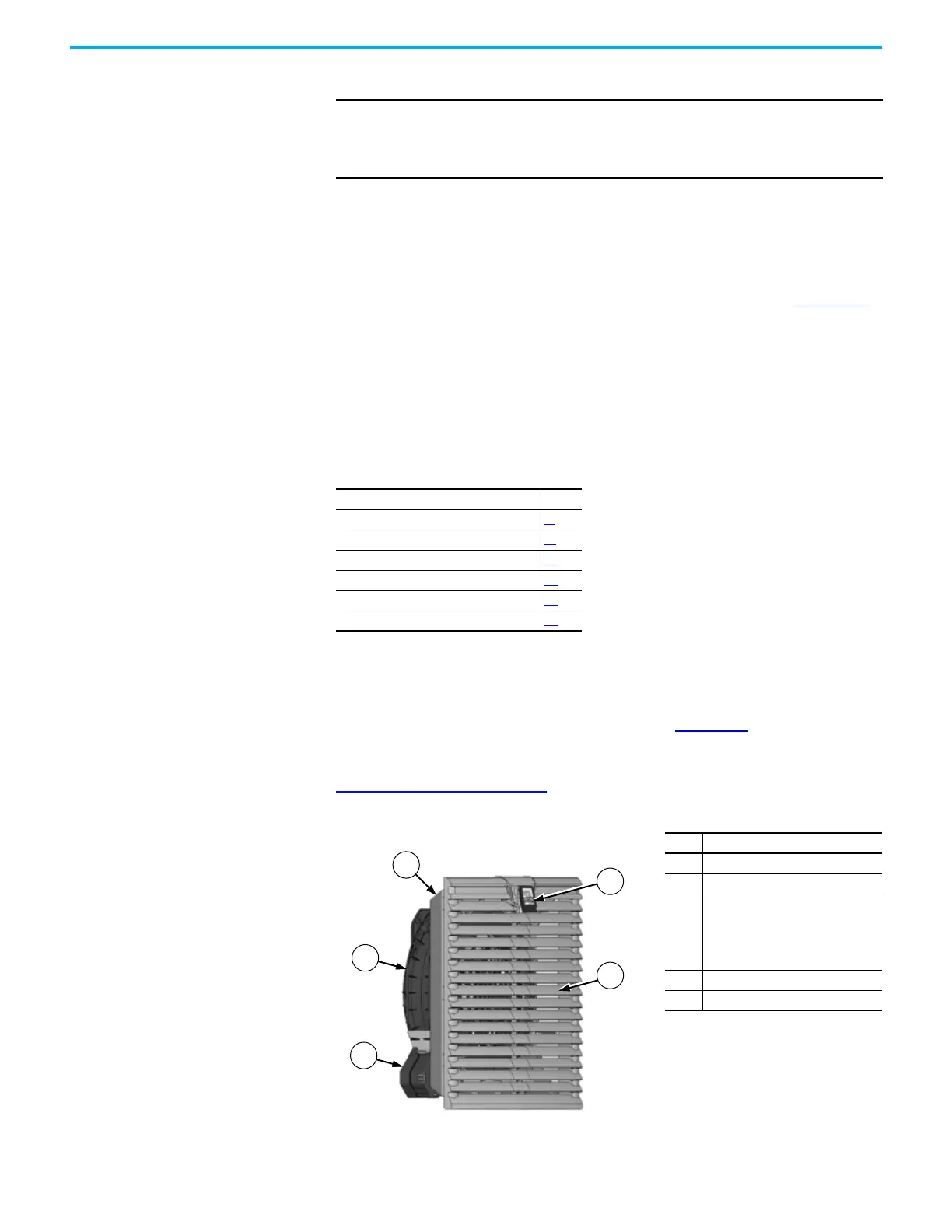
IP21/IP54 Door Fan/Vent Assembly
To replace the IP21/IP54 door fan/vent assembly (Figure 100), use the following
procedure. This procedure applies to multiple types door fan/vent assemblies.
For the catalog number of the replacement part for your product, see
Replacement Parts on page 111
.
IMPORTANT
It is recommended that you wait 5 minutes before cycling power
disconnect switches. This recommendation applies to both Off-to-On
and On-to-Off transitions. Rapid power cycling can result in equipment
damage.
Replaceable Part Page
IP21/IP54 Door Fan/Vent Assembly 117
IP21/IP54 Door Vent 121
IP21/IP54 Door Vent Filter Media 122
IP21/IP54 Small Roof Vent Filter Media 123
IP54 Large Roof Vent Filter Media 124
Sine-wave Filter Reactor Cooling Fan 125
Figure 100 - IP21/IP54 Door Fan/Vent Assembly
Item Description
1 Vent containing filter media
2 Fan housing
3
Power connection (can be
positioned at other corners by
rotating the fan housing 90° from
the position shown, but not to 180°
from the position shown)
4 Vent cover
5 Vent cover release tab

 Loading...


