58 Rockwell Automation Publication 750-IN118A-EN-P - May 2021
Chapter 3 Mechanical and Electrical Installation
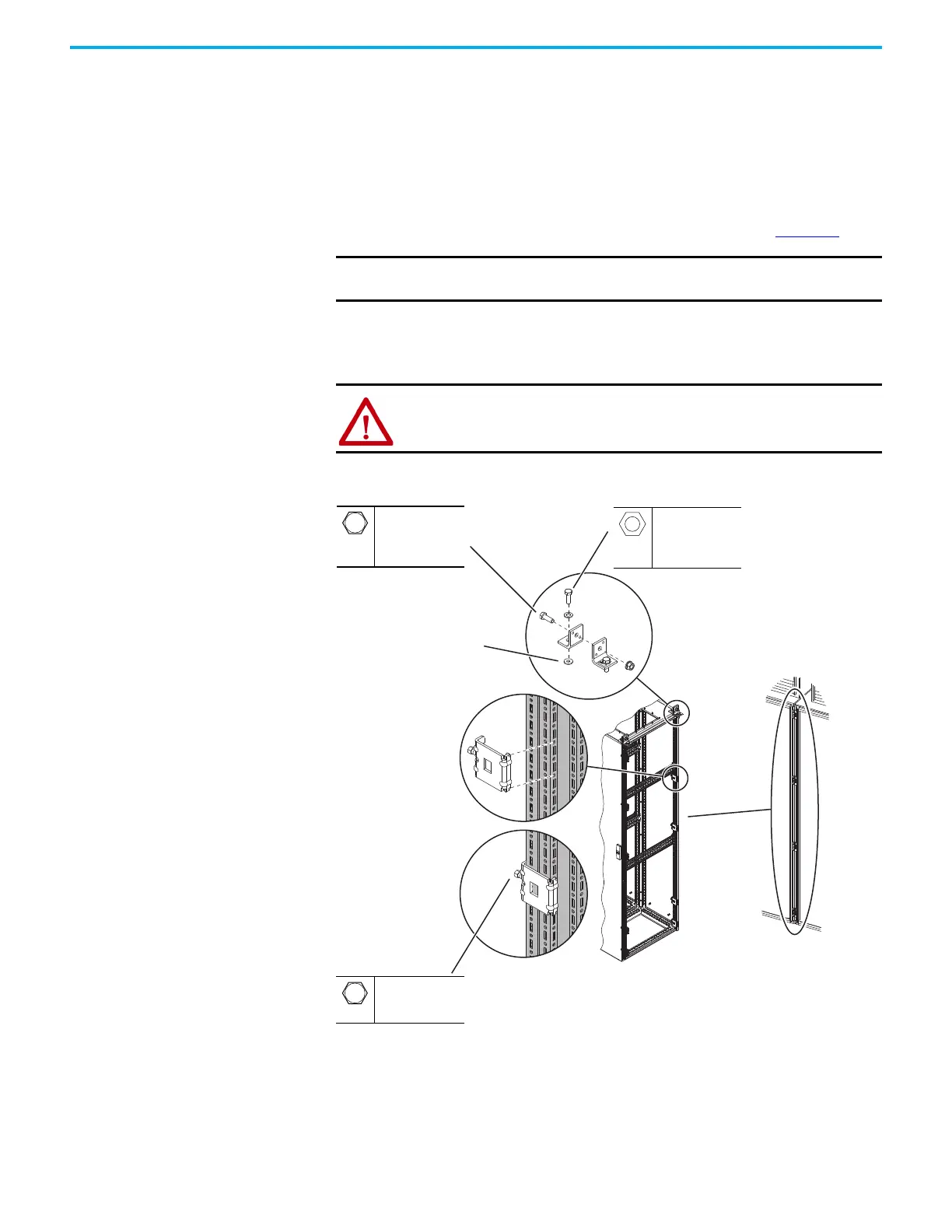
Top Brackets and Frame Clamps
When two bays are joined with top brackets and frame clamps, two top bracket
sets and nine frame clamps are used to join the bays. To install this bay joining
hardware, use the following procedure.
1. Make sure that the two sides of the joining are aligned, level, and pushed
together tightly.
2. Attach the angled brackets on top of the bays as shown in Figure 54
.
3. Install the bolts that join each pair of angle brackets and tighten.
4. Place and tighten the frame clamps, clamping the side frames of the bays
together.
Figure 54 - Joining Bays with Top Brackets and Frame Clamps
IMPORTANT
The paint-piercing rubber washers are required for both grounding
purposes and to meet the enclosure rating.
ATTENTION: Do not attempt to lift bays that are joined with this hardware.
Paint-piercing rubber washer
Bay doors omitted for clarity
Frame clamps
Top bracket set
M12
19 mm
20.0 N•m
(177 lb•in)
–
–
9.0 N•m (79 lb•in)
M12
19 mm
42.4 N•m
(375 lb•in)
Side 1 of
joining
Side 2 of
joining

 Loading...


