30 Rockwell Automation Publication 750-IN118A-EN-P - May 2021
Chapter 1 Product Overview
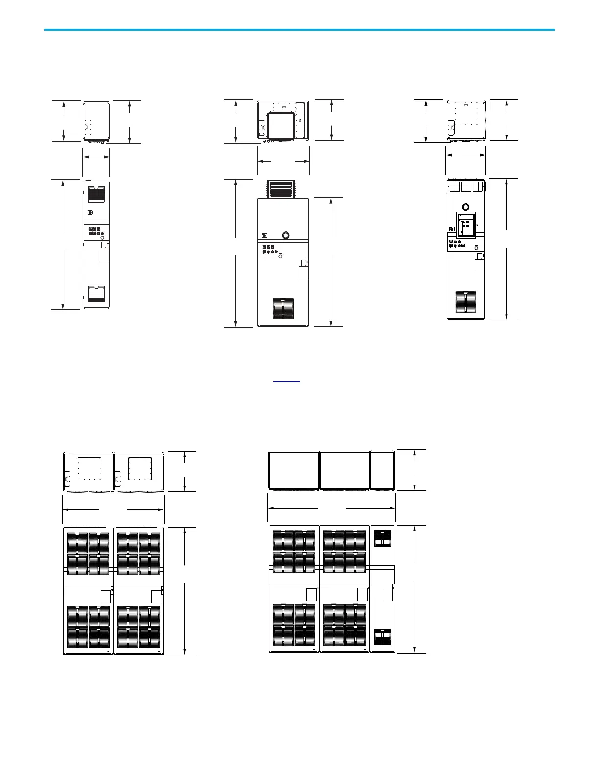
Frame 9
Figure 26 - Frame 9 Configured Input Bay
with Control-only (No Input Protection)
Figure 27 - Frame 9 Configured Input Bays with a
Roof Exhaust Vent
The approximate dimensions for Frame 9 configured
input bays with a roof exhaust vent apply to the
following bays:
• Configured input bay with input fuses, top entry (bay
that is shown in Figure 27
)
• Configured input bay with input fuses, bottom entry
• Configured input bay with circuit breaker, bottom
entry
Figure 28 - Frame 9 Configured Input Bay
with Input Circuit Breaker, Top Entry
647.2 mm
(25.48 in.)
600.0 mm
(23.62 in.)
400.0 mm
(15.75 in.)
800.0 mm
(31.50 in.)
642.0 mm
(25.28 in.)
2288.5 mm
(90.09 in.)
2000.0 mm
(78.74 in.)
600.0 mm
(23.62 in.)
2210.0 mm
(87.01 in.)
600.0 mm
(23.62 in.)
600.0 mm
(23.62 in.)
642.0 mm
(25.28 in.)
Figure 29 - Frame 9 Configured Output Bays, Top Exit
The Frame 9 configured output bays with top entry are a
section of two bays that are connected and shipped together.
Figure 30 - Frame 9 Configured Output Bays, Bottom Exit
The Frame 9 configured output bays with bottom entry are a section
of three bays that are connected and shipped together. This includes
two output filter bays on the left and an exit wire bay on the right.
2000.0 mm
(78.74 in.)
1600.0 mm
(62.99 in.)
600.0 mm
(23.62 in.)
600.0 mm
(23.62 in.)
2000.0 mm
(78.74 in.)
2000.0 mm
(78.74 in.)

 Loading...


