EasyManuals Logo

Rockwell Automation Allen-Bradley PowerFlex 755T Installation Instructions

Rockwell Automation Allen-Bradley PowerFlex 755T
130 pages
To Next Page IconTo Next Page
To Previous Page IconTo Previous Page
Page #52 background imageLoading...
Page #52 background image
52 Rockwell Automation Publication 750-IN118A-EN-P - May 2021
Chapter 3 Mechanical and Electrical Installation
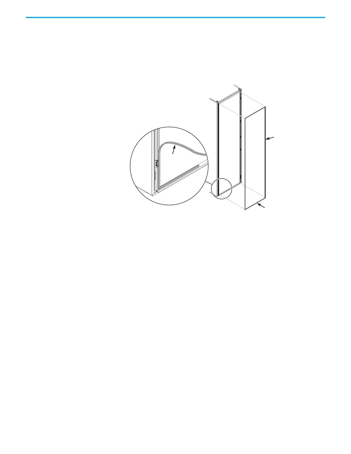
Apply a Gasket at the Joining Location
1. At the end of the bay lineup, where you are adding a bay, apply the gasket
in one continuous strip around the mating surface of the section. Seam
the gasket at the approximate middle of the bottom of the mating
surface.
Figure 48 - Applying the Gasket to the Mating Surface
Gasket
Gasket
Seam
location

Table of Contents

Other manuals for Rockwell Automation Allen-Bradley PowerFlex 755T

Questions and Answers:

Question and Answer IconNeed help?

Do you have a question about the Rockwell Automation Allen-Bradley PowerFlex 755T and is the answer not in the manual?

Rockwell Automation Allen-Bradley PowerFlex 755T Specifications

General IconGeneral
BrandRockwell Automation
ModelAllen-Bradley PowerFlex 755T
CategoryDC Drives
LanguageEnglish

Related product manuals