60 Rockwell Automation Publication 750-IN118A-EN-P - May 2021
Chapter 3 Mechanical and Electrical Installation
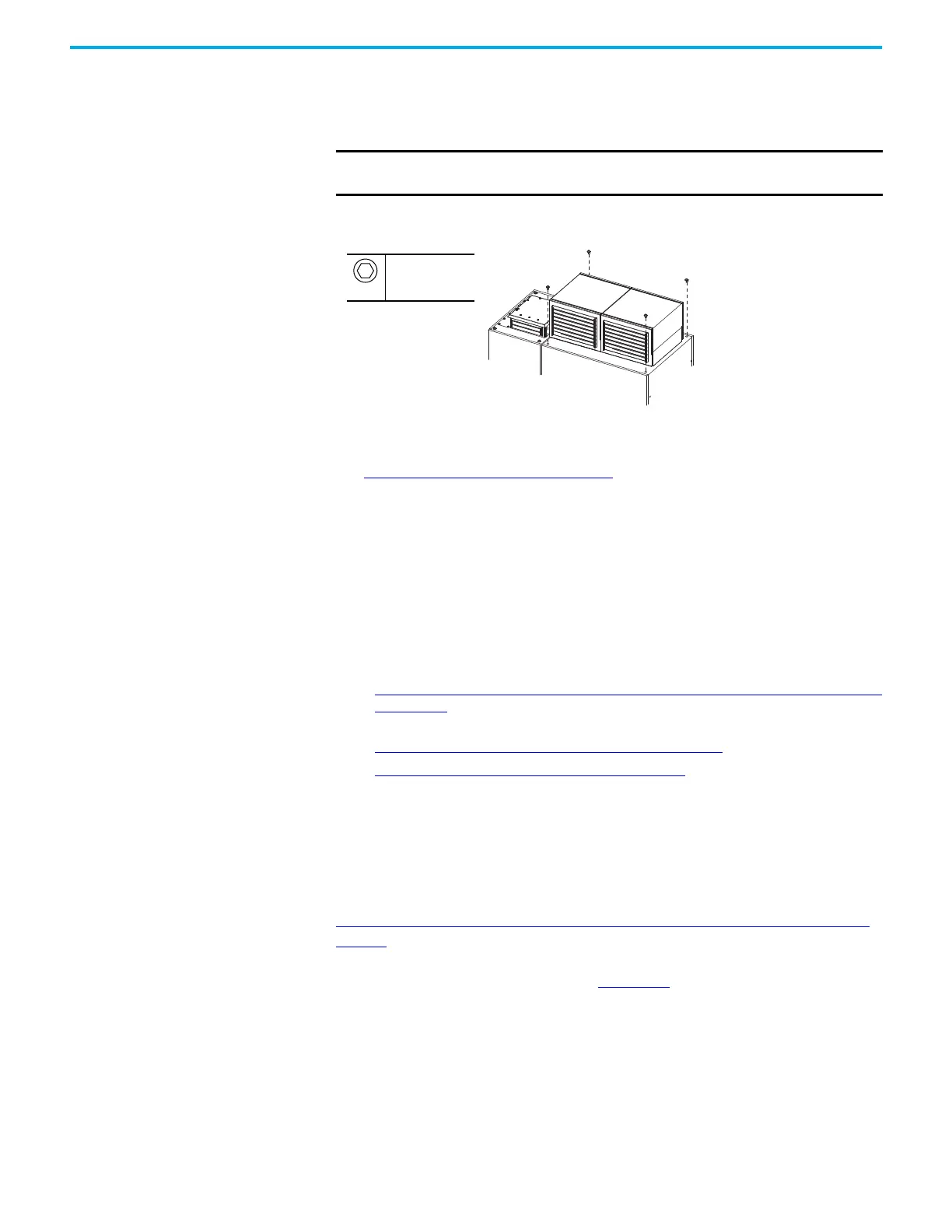
Secure Roof Assemblies Use the hardware supplied with the roof assemblies to secure the roof
assemblies to the bays. The screws that are provided are M12 screws with
integral paint-piercing rubber washers.
Figure 56 - Securing Roof Assemblies to Bays
Secure Floor Mounting
Hardware to the Floor
See Floor Mounting Options on page 40. See the drawing package that came
with your product for the locations of any conduit openings on the bottom of
your bay.
Make Bay-to-Bay Electrical
Connections
After all bays are mechanically joined and anchored to the mounting surface,
electrically connect the bays together. During this step, make only the bay-to-
bay connections, not connections to the customer power source or motor.
See the following sections to make the bay-to-bay electrical connections:
• Electrical Connections Made to Each Configured Bay During Installation
on page 61. This section provides references to the hardware used to
make the connections.
• Component and Connection Locations on page 64
.
• Bay to Bay Connection Hardware on page 84
.
• The drawings and schematics package that came with your product.
Access the Drive Control Pod
To determine if you must make connections to the drive control pod, see
Electrical Connections Made to Each Configured Bay During Installation on
page 61. If you must make connections to the drive control pod during
installation, see the PowerFlex 750-Series Products with TotalFORCE Control
Installation Instructions, publication 750-IN100
.
IMPORTANT
The paint-piercing rubber washers are required for both grounding
purposes and to meet the bay rating.
M12
19 mm
20 N•m (177 lb•in)

 Loading...


