86 Rockwell Automation Publication 750-IN118A-EN-P - May 2021
Chapter 3 Mechanical and Electrical Installation
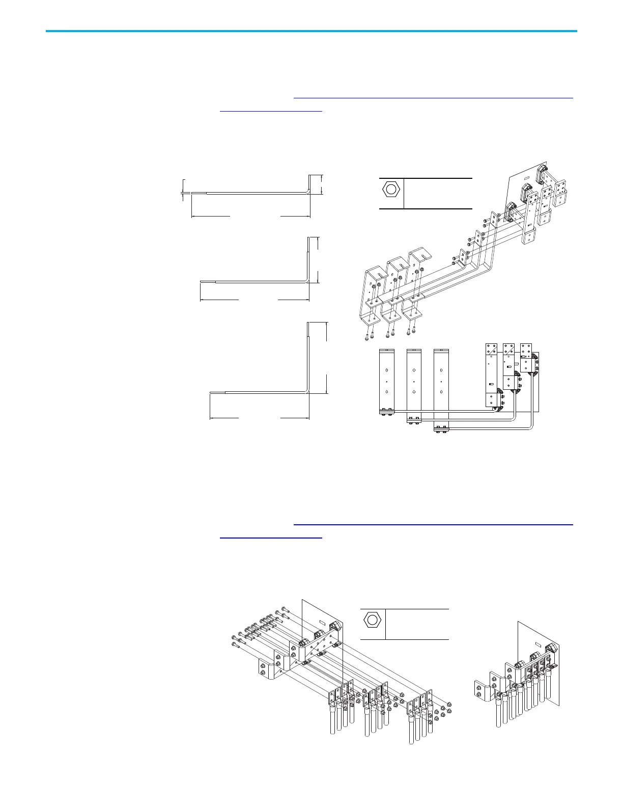
Flexibar Flexible Busbar Connection Hardware
To determine if you must make a connection using this hardware during
installation, see Electrical Connections Made to Each Configured Bay During
Installation on page 61. This hardware is used to make the power connection
from some types of configured input bay to the drive input bay.
Figure 84 - Flexibar Connection Hardware (dimensions in mm [in.])
Barrel Lug to Drive Input Busbar Connection Hardware
To determine if you must make a connection using this hardware during
installation, see Electrical Connections Made to Each Configured Bay During
Installation on page 61. This hardware is used in the drive input bay to make
the power connection from some types of configured input bay to the drive
input bay. The cable length for this connection is 2.5…3 m (8…10 ft).
Figure 85 - Barrel Lug Connection to Drive Input Busbars
685.6
[26.99]
495.31
[19.50]
754.6
[29.71]
314.5
[12.38]
821.6
[32.35]
133.7
[5.26]
10
[0.39]
M10
40 mm
100 N•m (885 lb•in)
M10
40 mm
100 N•m (885 lb•in)

 Loading...


