EasyManuals Logo

Rockwell Automation Allen-Bradley PowerFlex 755T Installation Instructions

Rockwell Automation Allen-Bradley PowerFlex 755T
130 pages
To Next Page IconTo Next Page
To Previous Page IconTo Previous Page
Page #120 background imageLoading...
Page #120 background image
120 Rockwell Automation Publication 750-IN118A-EN-P - May 2021
Chapter 5 Service and Maintenance
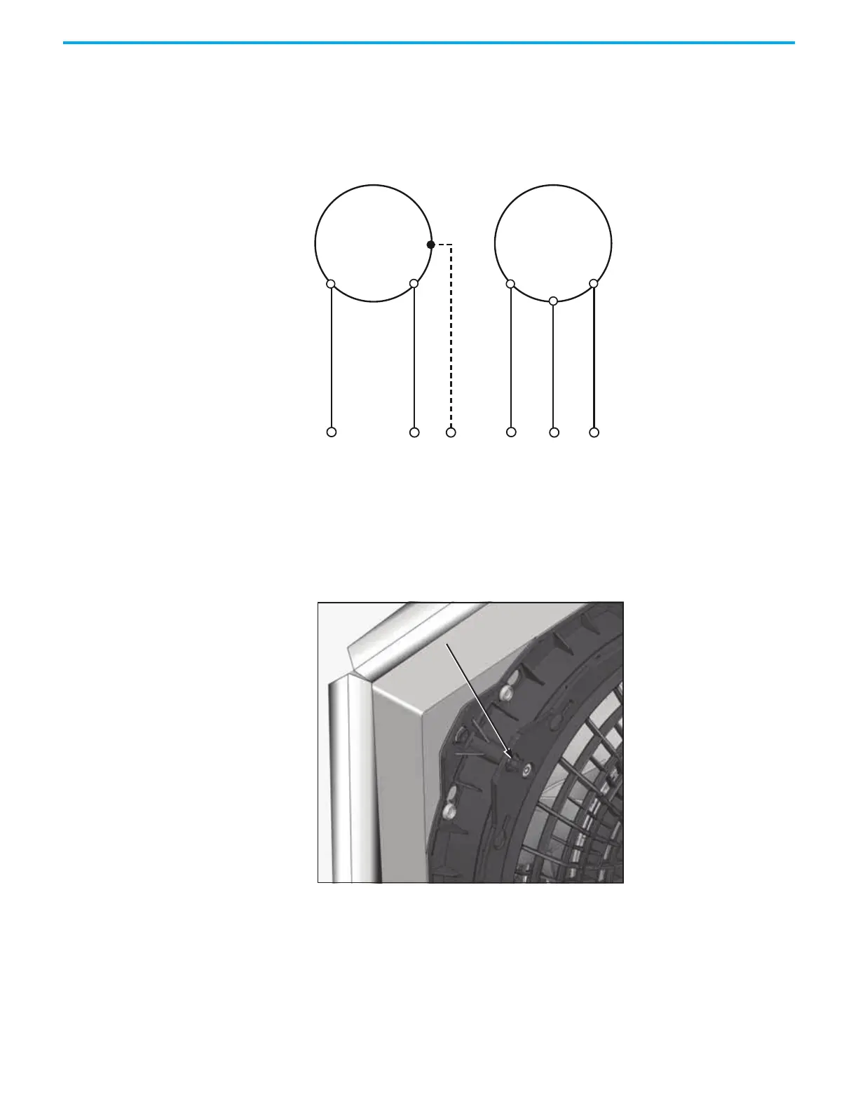
11. Insert the power connection cable with wire end ferrules into the spring
terminals. Use the wiring schematic for your type of fan.
Figure 106 - Fan Wiring Schematics
12. Attach the power connection cover.
13. To achieve EMC protection, the make sure the four contact foils at the
corners of the fan housing are protruded, helping prevent EMC contact
between the fan components and other components in the bay.
Figure 107 - EMC Contact Foil in Protruded Position
M
1~
Rittal part 3245510Rittal part 3241110
L NPE
M
1~
L N P

Table of Contents

Other manuals for Rockwell Automation Allen-Bradley PowerFlex 755T

Questions and Answers:

Question and Answer IconNeed help?

Do you have a question about the Rockwell Automation Allen-Bradley PowerFlex 755T and is the answer not in the manual?

Rockwell Automation Allen-Bradley PowerFlex 755T Specifications

General IconGeneral
BrandRockwell Automation
ModelAllen-Bradley PowerFlex 755T
CategoryDC Drives
LanguageEnglish

Related product manuals