28 Rockwell Automation Publication 750-IN118A-EN-P - May 2021
Chapter 1 Product Overview
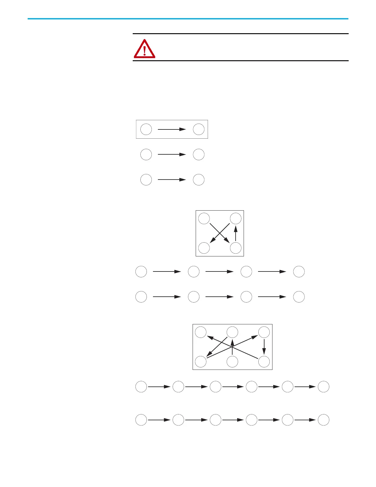
Fastener Torque Sequences
The following illustrates initial and final torque sequences for components
that are fastened to a heatsink by using two, four, and six screws. Initial torque
is 1/3 (33%) of final torque, except six-point mountings, which require 0.7 N
•m
(6 lb
•in) initial torque. The numeric illustration labels are for explanation.
Drive components do not contain these labels.
Figure 19 - Two-point Mounting
Figure 20 - Four-point Mounting
Figure 21 - Six-point Mounting
ATTENTION: Components can be damaged if initial tightening procedure is
not performed to specification.
Initial Sequence
Final Sequence
Initial Sequence
Final Sequence
4 65
4 65
1 2 3
1 2 3
2 4
1 5
6
3
Initial Sequence
Final Sequence
Do not exceed 0.7 N•m (6 lb•in) on initial torque of all six screws.

 Loading...


