38 Rockwell Automation Publication 750-IN118A-EN-P - May 2021
Chapter 2 Prepare for Installation
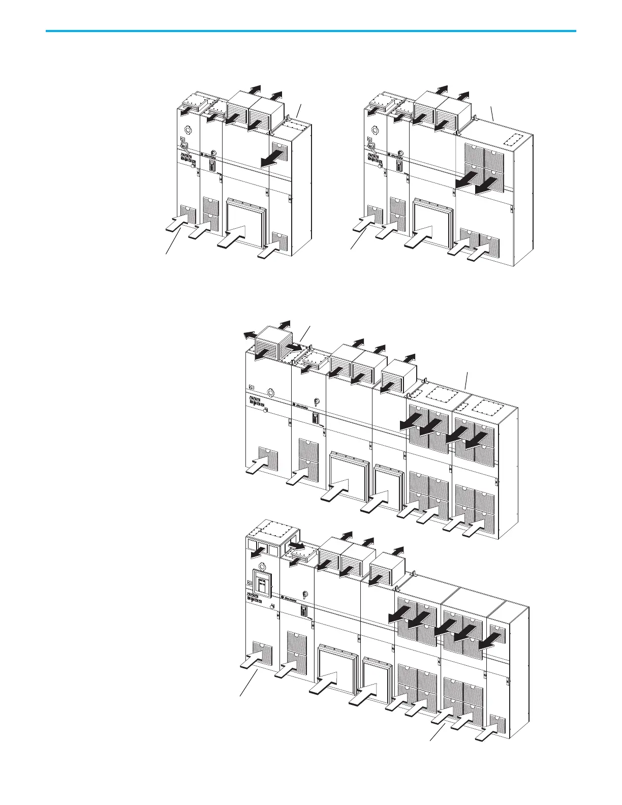
Figure 37 - Air-intake and Exhaust Locations: Examples of Frame 9 Lineups Including Configured Input
Bay, Drive Bays, and Configured Output Bays
Figure 36 - Air-intake and Exhaust Locations: Examples of Frame 8 Lineups Including Configured Input Bay, Drive Bays,
and Configured Output Bay
Configured input bay with
input circuit breaker, top entry
Configured input bay with
input circuit breaker, top entry
Configured output bay
with contactor only, top
Configured output bay with
sine-wave filter and
Configured input bay with input fuses, top entry
Configured output bays, top exit
Configured input bay with input
circuit breaker, top entry
Configured output bays, bottom exit
 Loading...


