44 Rockwell Automation Publication 750-IN118A-EN-P - May 2021
Chapter 2 Prepare for Installation
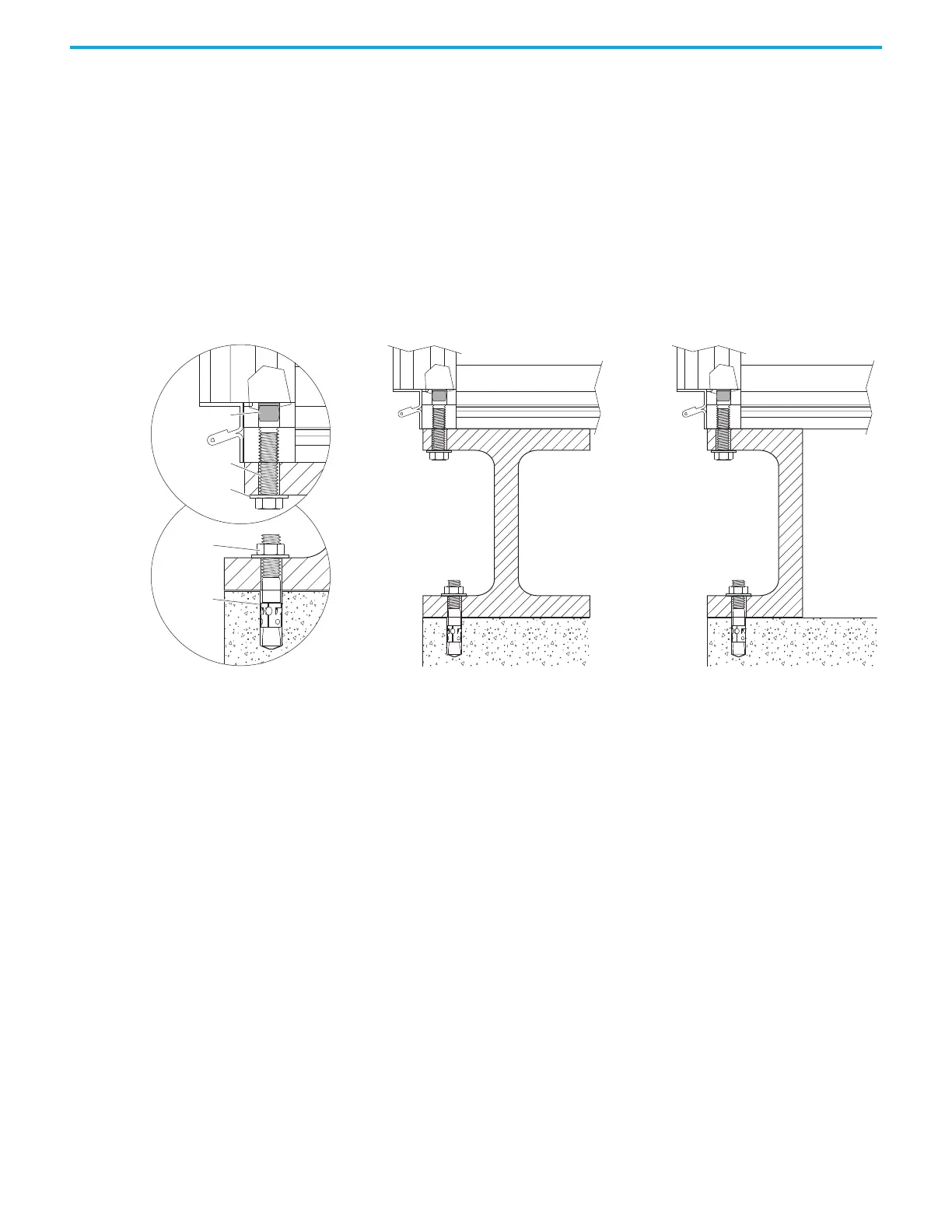
Structural Steel Mounting Configurations
Bays can be mounted directly to structural steel beams by using M12-1.75
screws threaded into the threaded corner holes. The bays must be secured to
the anchor bolts in all four corners by using M12 nuts and lock washers. Secure
the steel beam to the concrete floor by using M12 (0.5 in.) anchor bolts.
It is recommended that you orient the beams so that the I shape of the I beam
or the C shape of the C beam is visible when viewing the beam from the side of
the bay, not the front of the bay. This orientation allows for the addition of the
bay into the lineup, or removal of the bay from the lineup, using a forklift.
Figure 42 - Structural Steel Mounting Cross-section
Debris Plug
M12 Bolt
Lock Washer
M12 Nut
M12
Anchor Bolt

 Loading...


