ROCKWELL
COMMANDER
112/B/TC/TCA
MAINTENANCE MANUAL
SECTION I
GENERAL
lNFORMA TION
SECTION I
GENERAL INFORMATION
T
ABLE
OF
CONTENTS
GENERAL DESCRIPTION
.................••
PRINCIPAL DIMENSIONS
•..•....•.........•
General
.•.••..•...•....••.....•••••.•.•
Wing
••..•..............................
Horizontal
Stabilizer
and
Elevators
•.•.•••
Vertical
Stabilizer
and Rudder
..••.•...•.•
Fuselage
•..•......•...........•.••....•
Areas
•....•••..••..••..•.•.•..•...••••
FUSELAGE AND
WING
ST
AT
IONS
•.•.....•.•
AIRCRAFT STRUCTURES
••.•...••.•
,
•.•...•
Fuselage
•••••••.••••••.••..•...•.•.••••
GENERAL DESCRIPTION
Page
1-1
1-1
1-1
1-3
1
..
3
1-3
1
..
3
1-3
1-3
1-3
1-3
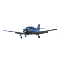
These
aircraft
are
low-wing,
single-engine
aircraft
designed
for
business
and
pleasure.
The
Models
112/B
are
powered
by a
Lycoming
IO-360-C1D6,
200-
horsepower
engine while
the
Models
112TC/TCA
are
powered
by
a Lycoming
T0-360-C1A6D,
21D-horse-
powered
engine.
These
aircraft
use
a
Hartzell
2-
blade,
constant-speed
propeller.
Structural
integrity,
flight
safety,
and
minimum
maintenance
requirements
are
assured
by
the
construction
and
design
of
the
ma-
jor
airframe
components.
The
wing
design
and
its
position
in
relation
to
the
fuselage
provides
the
best
capability
and
aircraft
controllability
desired
for
optimum
performance.
The
design
concept
of
the
aircraft
embodies
maximum
safety,
minimum
main-
tenance
requirements
and
ease
of
accomplishing
nec-
essary
maintenance
and
servicing.
Access
covers,
doors,
and
quick opening engine cowling
provide
easy
access
to
aircraft
and
engine
systems
components.
The
retractable
tricycle
landing
gear
is
operated
hy-
draulically
during
normal
operation.
Passenger
and
pilot
comfort
are
assured
by
the
design of
the
seating
and
interiors,
which
are
completely
insulated
and
up-
holstered
for
noise
abatement,
warmth
and
appearance.
The
cabin
will
seat
up
to
three
passenger
s
in
addition
Wing
...................................
.
Empennage
••....••.•.•.•..............•
AIRCRAFT SYSTEMS
•.••......••.....•....
Hydraulic
System
•.•..•••......•..••....
Powe r
Plant
•.•.•.••••.•.••..•..•....•.•
Fuel
System
.•.....•...........•.•......•
Landing
Gear,
Wheels, and
Brakes
•.....•
Flight
Controls
••.......................
Instruments
•...•••.•.•........•....••..
Heating and Ventilation
.•.•...........••.
Electrical
System
•.•.....••.......•.....
Page
1-6
1-6
1-6
1-6
1-6
1-7
1-7
1-7
1-7
1-7
1-8
to
the
pilot.
Entrance
doors
located
on both
sides
of
the
fuselage
provide
access
to
the
cabin
area.
A
baggage
compartment,
which
contains
22 cubic
feet
of
storage
space,
is
located
aft
of
the
rear
seats
and
is
accessible
through
a
door
on
the
left
side
of
the
fuselage,
or
from
the
rear
seats.
PRINCIPAL
DIMENSIONS
GENERAL
Wing Span
Model 112
• . • . • . . . . . .
393.00
inches
(32
'
-9
")
Model
112B/TC/TCA
••
427.20
inches
(35
'-7.20")
Overall
Length
300.50
inches
(25
'
.0.50")
Height
to
Top of
Vert.
Stab 101. 00
inches
(8
'-5.00")
Main
Gear
Tread
Model 112
....•.•..•
128.44
inches
(10
'
-8.
44
It)
Mode1112B/TC/TCA
131. 40
inches
(10'
-11.. 40")
Main
Gear
to
Nose
Gear
Model 112
•...•••.•..
82.97
inches
(6
'-10.97")
Mode1112B/TC/TCA..
82.50
inches
(6
'_10. 50
ft
)
Gross
Weight
Model 112
(thru
SiN
125)
••.•.••.••
2550
lbs.
1-1
Copyright Commander Owners Group 2013 All Rights Reserved
**unofficial copy**
 Loading...