EasyManua.ls Logo

Rockwell Commander 112 - INSTRUMENT SYSTEM MAINTENANCE; FLIGHT INSTRUMENTS

Rockwell Commander 112
293 pages
Print Icon
To Next Page IconTo Next Page
To Previous Page IconTo Previous Page
Loading...
SECTION vm
INSTRUMENTS
MAINTENANCE
MANUAL
ROCKWELL
COMMANDER
l12/B/TC/TCA
3
4
5
2
19
13
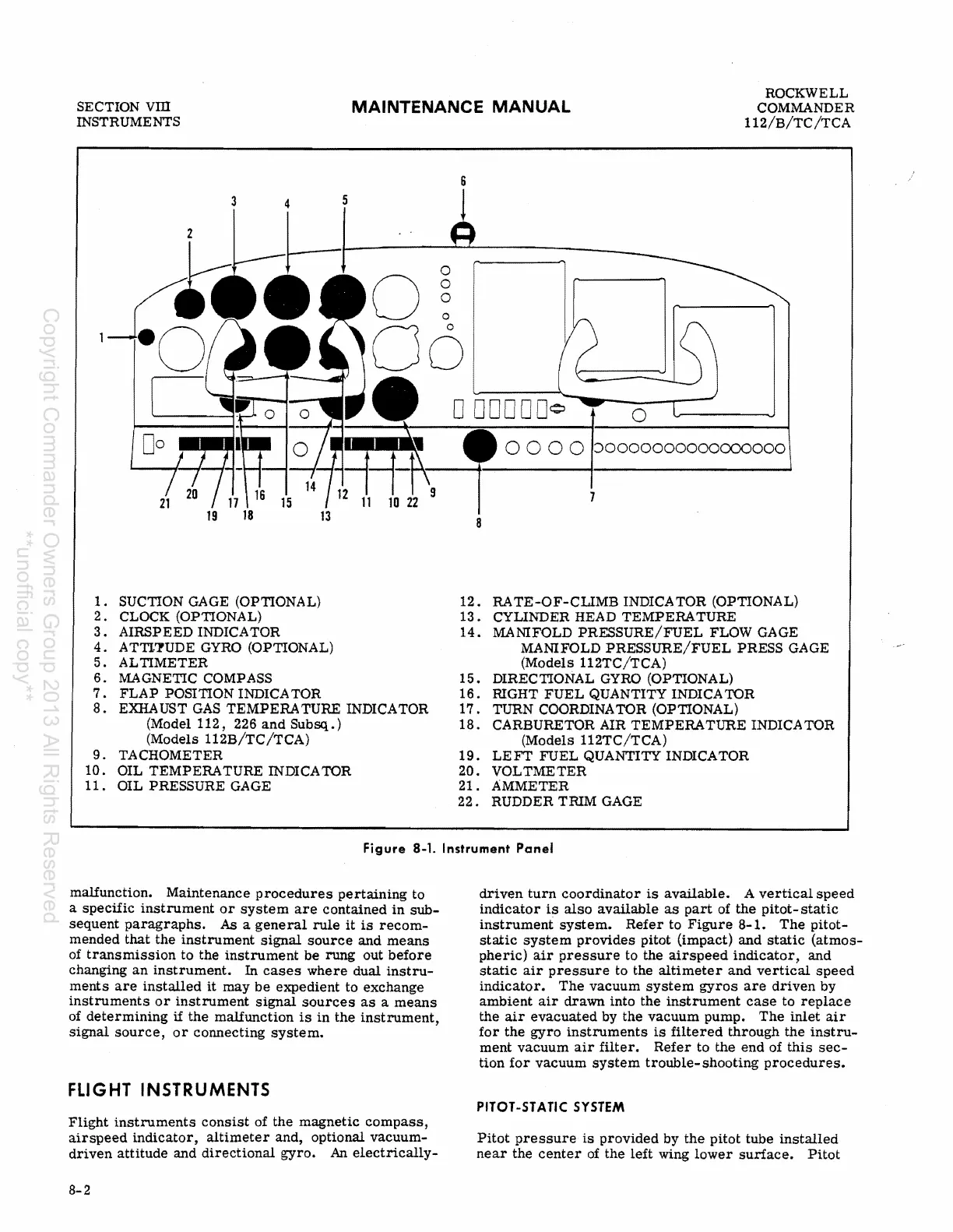
1.
SUCTION GAGE (OPTIONAL)
2.
CLOCK (OPTIONAL)
3.
AIRSPEED INDICATOR
4.
ATTI'l"UDE GYRO (OPTIONAL)
5.
ALTIMETER
6.
MAGNETIC COMPASS
7.
FLAP
POSITION INDICA TOR
8.
EXHAUST
GAS
TEMPERATURE
INDICATOR
(Model
112,
226
and
Subsq.)
(Models
112B/TC/TCA)
9.
TACHOMETER
10.
OIL TEMPERATURE INDICATOR
11.
OIL PRESSURE GAGE
0000
7
8
12.
RATE-OF-CUMB
INDICATOR (OPTIONAL)
13.
CYLINDER HEAD TEMPERATURE
14.
MANIFOLD
PRESSURE/FUEL
FLOW GAGE
MANIFOLD
PRESSURE/FUEL
PRESS GAGE
(Models
112TC/TCA)
15.
DIRECTIONAL GYRO (OPTIONAL)
16.
RIGHT
FUEL
QUANTITY INDICATOR
17.
TURN COORDINA TOR (OPTIONAL)
18.
CARBURETOR AIR
TEMPERATURE
INDICA TOR
(Models
112TC/TCA)
19.
LEFT
FUEL QUANTITY INDICATOR
20.
VOLTMETER
21.
AMMETER
22.
RUDDER TRIM GAGE
Figure
8-1.
Instrument
Panel
malfunction.
Maintenance
procedures
pertaining
to
a
specific
instrument
or
system
are
contained
in
sub-
sequent
paragraphs.
As a
general
rule
it
is
recom-
mended
that
the
instrument
signal
source
and
means
of
transmission
to
the
instrument
be
rung out
before
changing
an
instrument.
In
cases
where
dual
instru-
ments
are
installed
it
may
be
expedient
to
exchange
instruments
or
instrument
signal
sources
as
a
means
of
determining
if
the
malfunction
is
in
the
instrument,
signal
source,
or
connecting
system.
FLIGHT
INSTRUMENTS
Flight
instruments
consist
of
the
magnetic
compass,
airspeed
indicator,
altimeter
and,
optional
vacuum-
driven
attitude
and
directional
gyro.
An
electrically-
8-2
driven
turn
coordinator
is
available.
A
vertical
speed
indicator
is
also
available
as
part
of
the
pitot-
static
instrument
system.
Refer
to
Figure
8-1.
The
pitot-
static
system
provides
pitot (impact)
and
static
(atmos-
pheric)
air
pressure
to the
airspeed
indicator,
and
static
air
pressure
to the
altimeter
and
vertical
speed
indicator.
The
vacuum
system
gyros
are
driven
by
ambient
air
drawn
into
the
instrument
case
to
replace
the
air
evacuated
by
the
vacuum
pump.
The
inlet
air
for
the
gyro
instruments
is
filtered
through
the
instru-
ment
vacuum
air
filter.
Refer
to
the
end
of
this
sec-
tion
for
vacuum
system
trouble-
shooting
procedures.
PfTOT-STATIC
SYSTEM
Pitot
pressure
is
provided
by
the
pitot
tube
installed
near
the
center
of
the
left
wing
lower
surface.
Pitot
Copyright Commander Owners Group 2013 All Rights Reserved
**unofficial copy**

Table of Contents