EasyManua.ls Logo

Rockwell Commander 112 - Throttle

Rockwell Commander 112
293 pages
Print Icon
To Next Page IconTo Next Page
To Previous Page IconTo Previous Page
Loading...
ROCKWELL
COMMANDER
112/B/TC/TCA
MAINTENANCE
MANUAL
SECTION
IV
POWER PLANT
AND
PROPELLER
ON
0
rD
5
OFF
C F
HI
It
0
U
I
l
l
C
D
L
H
T P
I
H
It
M
N
It
0
I
D
0
P
X
U
T
T
C
T
It
U
T
L
P
R
E
M
E
I
l
H D
E
0 L
A
T
E
to
N
X24
1
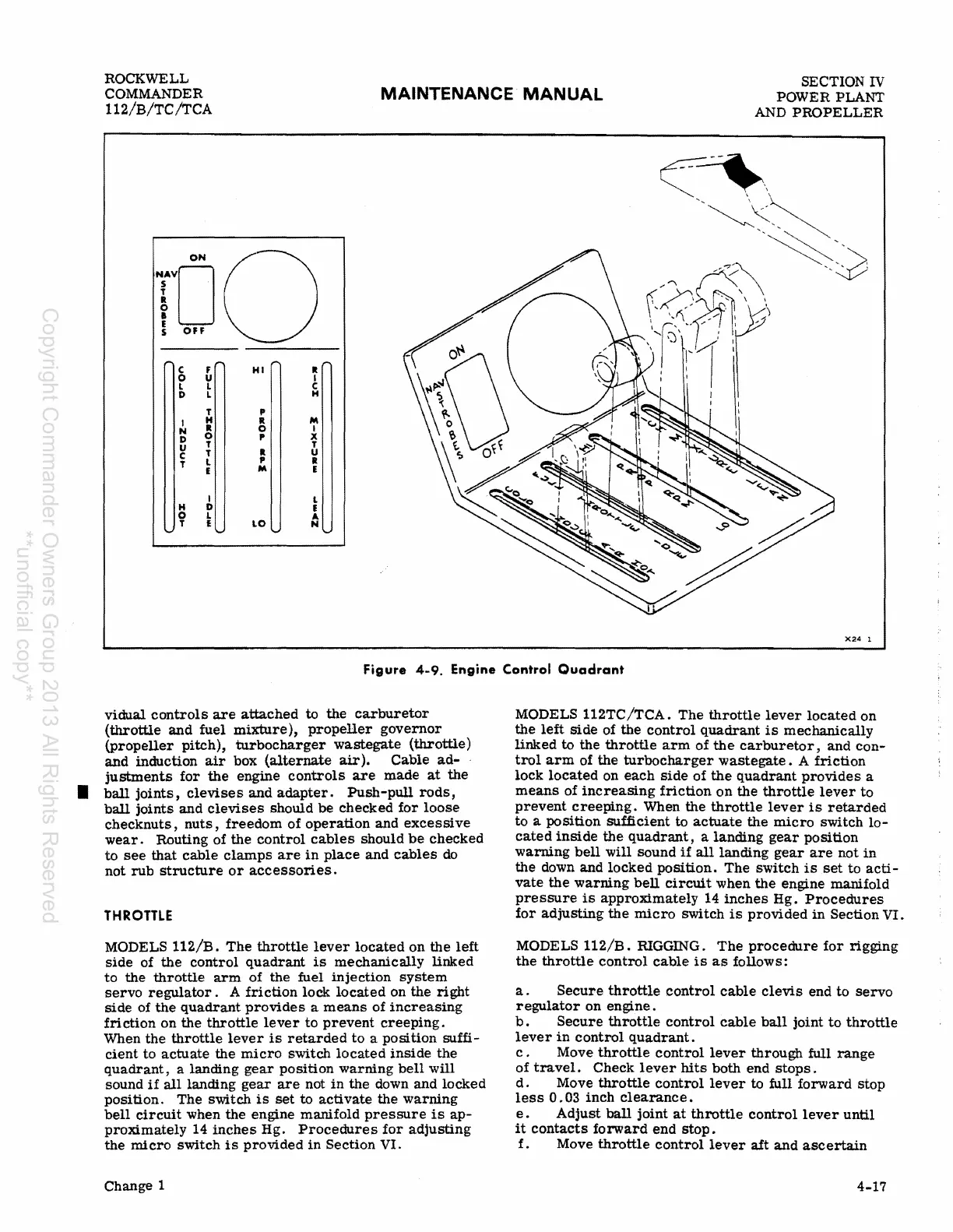
Figure
4-9.
Engine
Control
Quadrant
vidual
controls
are
attached
to
the
carburetor
(throttle
and
fuel
mixture),
propeller
governor
(propeller
pitch),
turbocharger
wastegate
(throttle)
and
induction
air
box
(alternate
air).
Cable
ad-
justments
for
the
engine
controls
are
made
at
the
•
ball
joints,
clevises
and
adapter.
Push-pull
rods,
ball
joints
and
clevises
should
be
checked
for
loose
checknuts,
nuts,
freedom
of
operation
and
excessive
wear.
Routing
of
the
control
cables
should
be
checked
to
see
that
cable
clamps
are
in
place
and
cables
do
not
rub
structure
or
accessories.
THROTTLE
MODELS
112/B.
The
throttle
lever
located
on
the
left
side
of
the
control
quadrant
is
mechanically
linked
to
the
throttle
arm
of
the
fuel
injection
system
servo
regulator.
A
friction
lock
located
on
the
right
side
of
the
quadrant
provides
a
means
of
increasing
friction
on
the
throttle
lever
to
prevent
creeping.
When
the
throttle
lever
is
retarded
to
a
position
suffi-
cient
to
actuate
the
micro
switch
located
inside
the
quadrant,
a
landing
gear
position
warning
bell
will
sound
if
all
landing
gear
are
not
in
the
down
and
locked
position.
The
switch
is
set
to
activate
the
warning
bell
circuit
when
the
engine
manifold
pressure
is
ap-
proximately
14
inches
Hg.
Procedures
for
adjusting
the
micro
switch
is
provided
in
Section
VI.
Change 1
MODELS
112TC/TCA.
The
throttle
lever
located
on
the
left
side
of
the
control
quadrant
is
mechanically
linked
to
the
throttle
arm
of
the
carburetor,
and
con-
trol
arm
of
the
turbocharger
wastegate.
A
friction
lock
located
on
each
side
of
the
quadrant
provides
a
means
of
increasing
friction
on
the
throttle
lever
to
prevent
creeping.
When
the
throttle
lever
is
retarded
to
a poSition
sufficient
to
actuate
the
micro
switch
lo-
cated
inside
the
quadrant,
a
landing
gear
position
warning
bell
will
sound
if
all
landing
gear
are
not
in
the
down
and
locked
poSition.
The
switch
is
set
to
acti-
vate
the
warning
bell
circuit
when
the
engine
manifold
pressure
is
approximately
14
inches
Hg.
Procedures
for
adjusting
the
micro
switch
is
provided
in
Section
VI.
MODELS
112/B.
RIGGING.
The
procedure
for
rigging
the
throttle
control
cable
is
as
follows:
a.
Secure
throttle
control
cable
clevis
end
to
servo
regulator
on
engine.
b.
Secure
throttle
control
cable
ball
joint
to
throttle
lever
in
control
quadrant.
c . Move
throttle
control
lever
through
full
range
of
travel.
Check
lever
hits
both
end
stops.
d.
Move
throttle
control
lever
to full
forward
stop
less
0.03
inch
clearance.
e.
Adjust
ball
joint
at
throttle
control
lever
until
it
contacts
forward
end
stop.
f.
Move
throttle
control
lever
aft
and
ascertain
4-17
Copyright Commander Owners Group 2013 All Rights Reserved
**unofficial copy**

Table of Contents